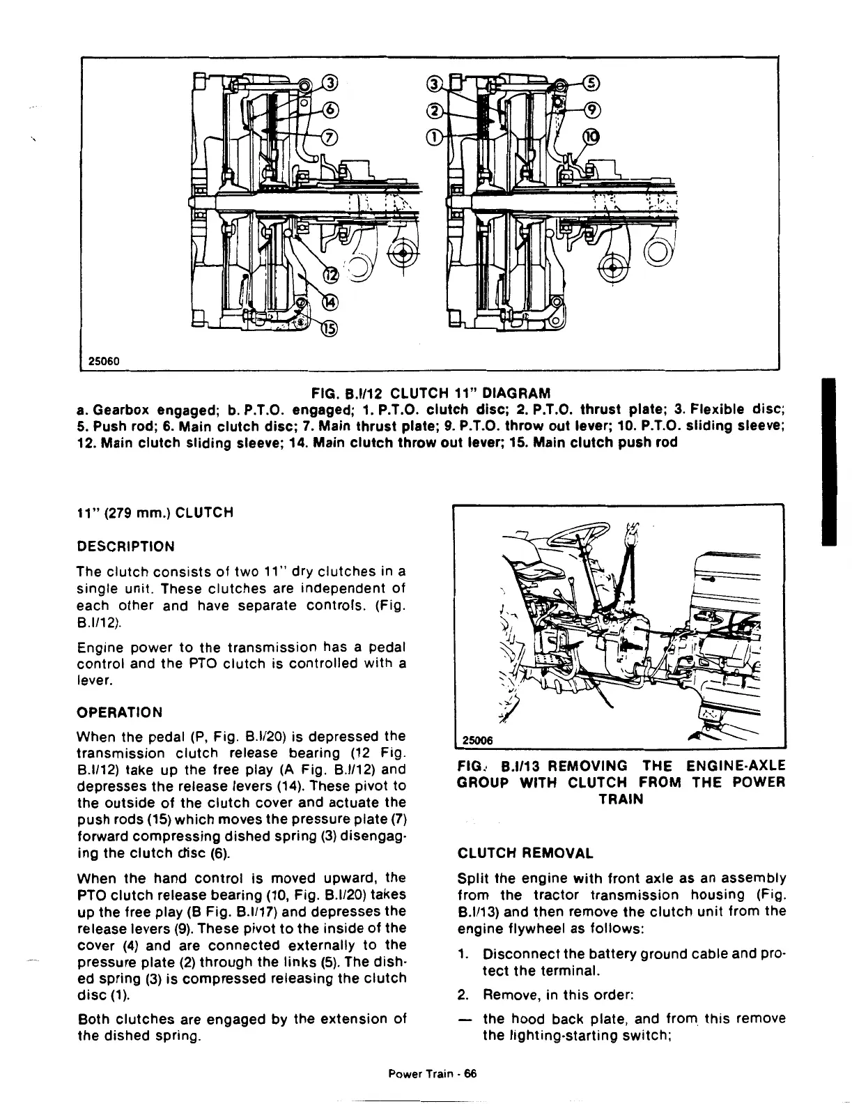
25060
FIG.
8.1112
CLUTCH
11"
DIAGRAM
a. Gearbox engaged; b. P.T.O. engaged; 1. P.T.O.
clutch
disc;
2.
P.T.O.
thrust
plate;
3.
Flexible
disc;
5.
Push rod;
6.
Main
clutch
disc;
7.
Main
thrust
plate;
9.
P.T.O.
throw
out
lever; 10. P.T.O.
sliding
sleeve;
12. Main
clutch
sliding
sleeve; 14. Main
clutch
throw
out
lever; 15. Main
clutch
push rod
11"
(279 mm.) CLUTCH
DESCRIPTION
The
clutch
consists
of
two
11" dry
clutches
in a
single
unit. These
clutches
are independent
of
each
other
and have separate controls. (Fig.
8.1/12).
Engine
power
to
the
transmission
has a pedal
control
and the
PTO
clutch
is
controlled
with
a
lever.
OPERATION
When the pedal
(P,
Fig.
8.1120)
is
depressed the
transmission
clutch
release bearing
(12
Fig.
8.1/12)
take up the free play (A Fig.
8.1/12)
and
depresses the release levers
(14).
These pivot
to
the
outside
of
the
clutch
cover and actuate the
push rods
(15)
which
moves the pressure plate
(7)
forward
compressing
dished spring
(3)
disengag·
ing the
clutch
ctisc
(6).
When
the
hand
control
is
moved upward, the
PTO
clutch
release bearing (10, Fig. B.l/20) takes
up the free play (B Fig. B.l/17) and depresses the
release levers
(9).
These pivot
to
the
inside
of
the
cover
(4)
and are
connected
externally
to
the
pressure plate
(2)
through
the
links
(5).
The
dish·
ed spring
(3)
is
compressed releasing the
clutch
disc
(1).
Both
clutches
are engaged by the
extension
of
the
dished spring.
25006
FIG.· B.l/13 REMOVING THE ENGINE·AXLE
GROUP WITH CLUTCH FROM THE POWER
TRAIN
CLUTCH REMOVAL
Split
the engine
with
front
axle as an assembly
from
the
tractor
transmission
housing
(Fig.
8.1113)
and then remove the
clutch
unit
from the
engine flywheel as
follows:
1.
Disconnect
the battery ground cable and pro·
teet
the
terminal.
2.
Remove, in
this
order:
the hood back plate, and
from
this
remove
the
lighting·starting
switch;
Power Train ·
66
 Loading...

