85320
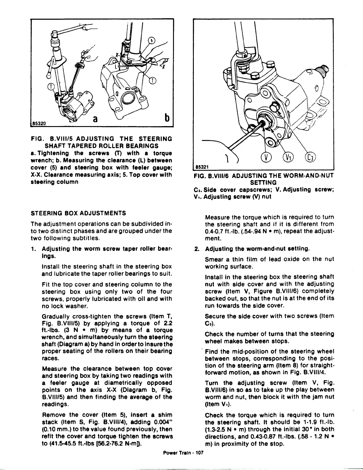
FIG. B.VIII/5 ADJUSTING THE STEERING
SHAFT TAPERED ROLLER BEARINGS
a.
Tightening the screws (T)
with
a torque
wrench; b. Measuring the clearance
(L)
between
cover
(5)
and steering box
with
feeler gauge;
X·X.
Clearance measuring axis;
5.
Top cover with
steering column
STEERING BOX ADJUSTMENTS
The adjustment operations can be subdivided in·
to
two
distinct
phases and are grouped under the
two
following subtitles.
1.
Adjusting the worm screw taper roller bear·
lngs.
Install the steering shaft in the steering box
and lubricate the taper roller bearings
to
suit.
Fit the top cover and steering column to the
steering box using only
two
of
the four
screws, properly lubricated with oil and with
no lock washer.
Gradually cross-tighten the screws (Item
T,
Fig. B.VIII/5) by applying a torque
of
2.2
ft.-lbs.
(3
N •
m)
by means
of
a torque
wrench, and simultaneously turn the steering
shaft (Diagram
a)
by hand In order
to
Insure the
proper seating
of
the rollers on their bearing
races.
Measure the clearance between
top
cover
and steering box by taking
two
readings with
a feeler gauge at diametrically opposed
points on the axis
X·X
(Diagram b, Fig.
B.VIII/5) and then finding the average
of
the
readings.
Remove the cover (Item
5),
insert a shim
stack (Item
S,
Fig. B.VIII/4), adding 0.004"
(0.10
mm.)
to
the value found previously, then
refit the cover and torque tighten the screws
to
(41.5-45.5
ft.·lbs [56.2·76.2
N-mD.
85321
FIG. B.VIII/6 ADJUSTING THE WORM·AND-NUT
SETTING
Ca.
Side cover capscrews;
V.
Adjusting screw;
v,.
Adjusting screw
(V)
nut
Measure the torque which is required to turn
the steering shaft and if it is different from
0.4·0.7 ft.-lb.
(.54-.94
N •
m),
repeat the adjust-
ment.
2.
Adjusting the worm-and-nut setting.
Smear a thin film
of
lead oxide on the nut
working surface.
Install in the steering box the steering shaft
nut with side cover and with the adjusting
screw (Item
V,
Figure B.VIII/6) completely
backed out, so that the nut is at the end
of
its
run towards the side cover.
Secure the side cover with two screws (Item
Ca).
Check the number
of
turns that the steering
wheel makes between stops.
Find the mid-position
of
the steering wheel
between stops, corresponding
to
the posi·
tion
of
the steering arm (Item
8)
for straight·
forward motion, as shown in Fig. B.VIII/4.
Turn the adjusting screw (Item
V,
Fig.
B.VIII/6) in so as
to
take up the play between
worm and nut, then block
it
with the jam nut
(Item V,).
Check the torque which is required to turn
the steering shaft. It should be 1·1.9 ft.-lb.
(1.3-2.5
N •
m)
through the initial
30
• in both
directions, and 0.43-0.87 ft.-lbs.
(.58·
1.2
N •
m)
In
proximity
of
the stop.
Power Train • 107
 Loading...

