B.IV BRAKES
85294
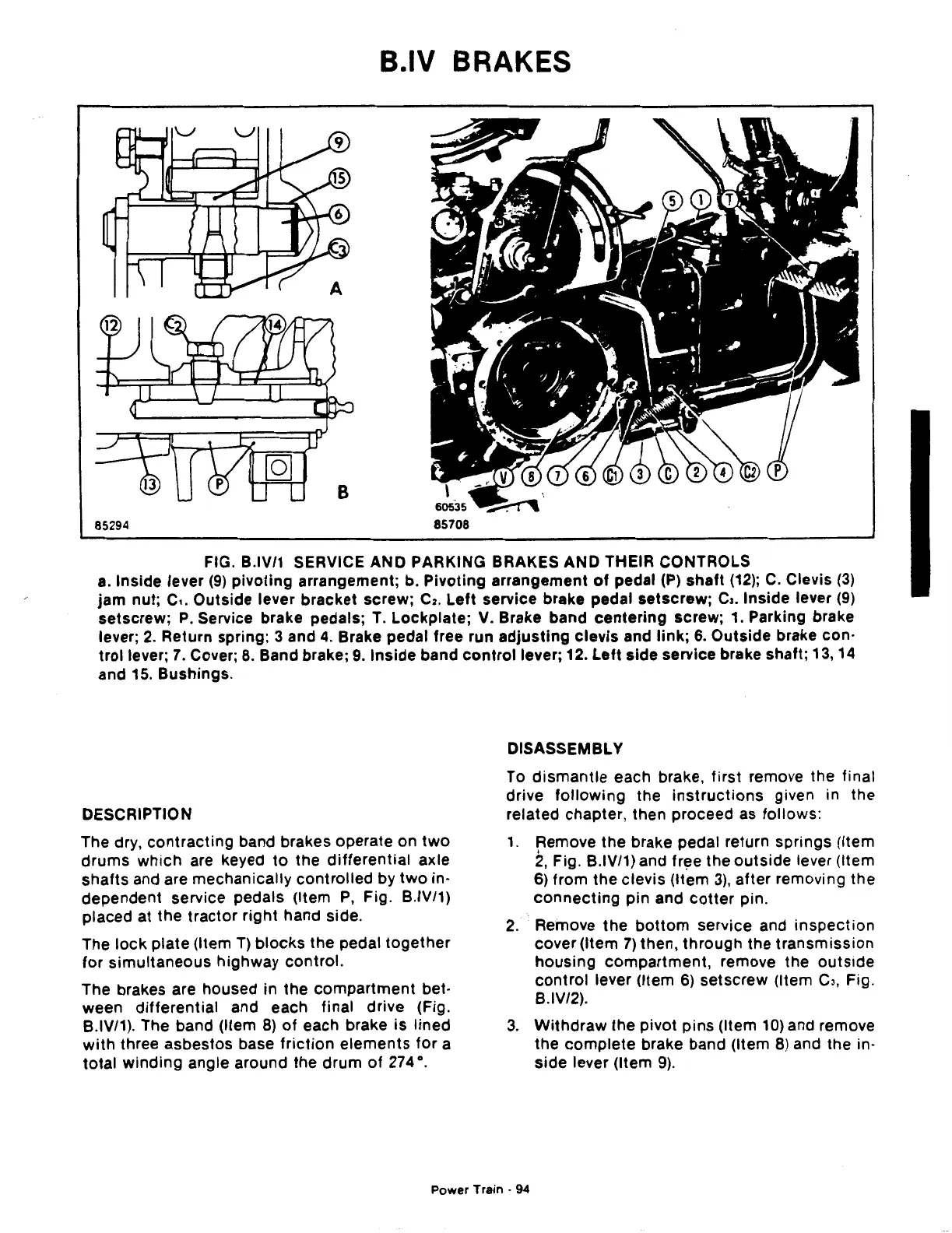
FIG. B.IV/1 SERVICE AND PARKING BRAKES AND THEIR CONTROLS
a.
Inside lever
(9)
pivoting
arrangement; b.
Pivoting
arrangement
of
pedal
(P)
shaft
(12);
C.
Clevis
(3)
jam
nut;
c,.
Outside lever bracket screw;
C2.
Left service brake pedal setscrew;
C3.
Inside lever
(9)
setscrew;
P.
Service brake pedals;
T.
Lockplate; V. Brake band
centering
screw; 1. Parking brake
lever;
2.
Return spring; 3 and
4.
Brake pedal free run
adjusting
clevis
and
link;
6.
Outside brake con·
trollever;
7.
Cover;
8.
Band brake;
9.
Inside
band
control
lever; 12. Left side service brake shaft; 13,
14
and 15. Bushings.
DESCRIPTION
The dry,
contracting
band brakes operate on
two
drums
which
are keyed
to
the
differential
axle
shafts
and are mechanically
controlled
by
two
in·
dependent service pedals (Item
P,
Fig. B.IV/1)
placed at the
tractor
right
hand side.
The
lock
plate (Item
T)
blocks
the pedal
together
for
simultaneous
highway control.
The brakes are housed in the
compartment
bet-
ween
differential
and each final drive (Fig.
B.IV/1). The band (Item
8)
of
each brake is
lined
with
three asbestos base
friction
elements
for
a
total
winding
angle around the
drum
of
274
°.
DISASSEMBLY
To
dismantle
each brake,
first
remove the final
drive
following
the
instructions
given in the
related chapter, then proceed as follows:
1.
Remove the brake pedal return springs (Item
2,
Fig. B.IV/1) and
fr~e
the
outside
lever (Item
6) from the clevis (Item
3),
after
removing the
connecting
pin and
cotter
pin.
2.
Remove
the
bottom
service and
inspection
cover (Item
7)
then,
through
the
transmission
housing
compartment,
remove the
outside
control
lever (Item
6)
setscrew
(Item
C3,
Fig.
B.IV/2).
3.
Withdraw
the pivot
pins
(Item
10)
and remove
the
complete
brake band (Item
8)
and the in·
side
lever (Item
9).
Power
Train·
94
 Loading...

