\
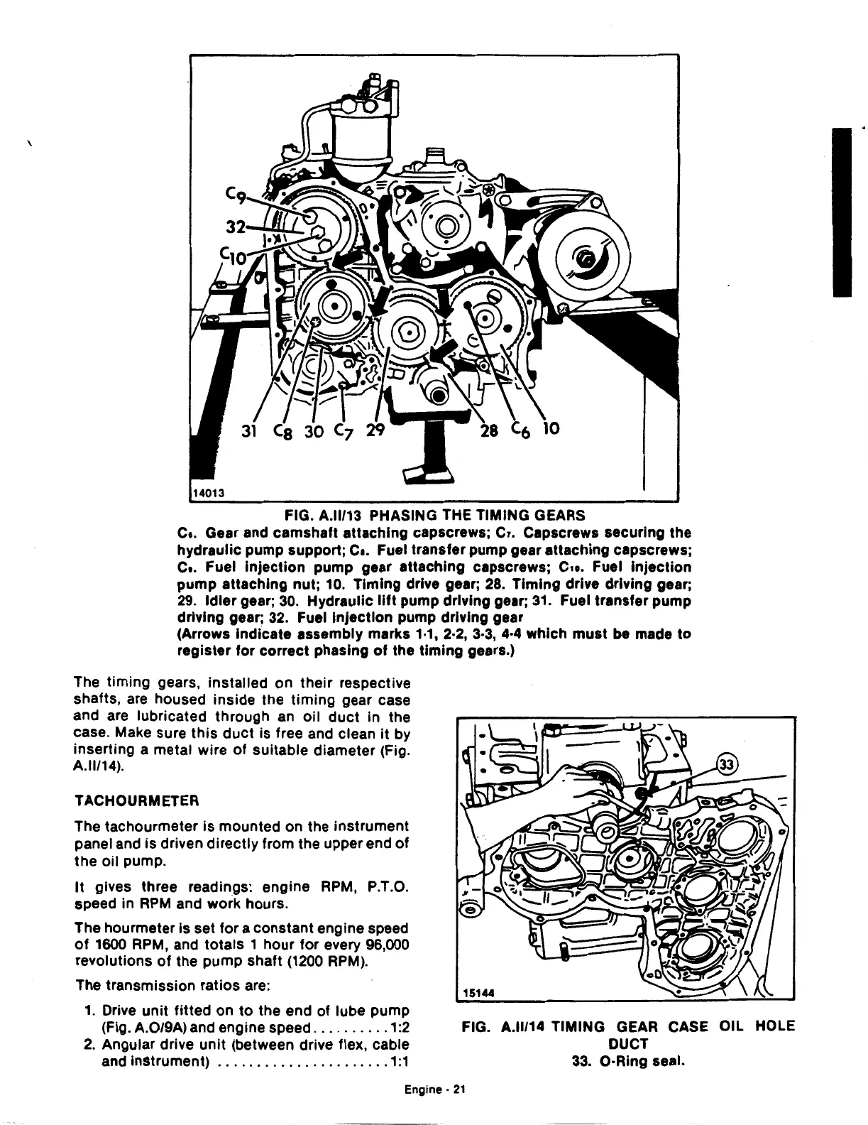
FIG. A.ll/13 PHASING THE TIMING GEARS
c..
Gear and camshaft attaching capscrews; Cr. Capscrews securing the
hydraulic pump support;
c
•.
Fuel transfer pump gear attaching capscrews;
c..
Fuel Injection pump gear attaching capscrews;
c,
•.
Fuel Injection
pump attaching nut; 10. Timing drive gear;
28.
Timing drive driving gear;
29.
Idler gear;
30.
Hydraulic lift pump driving gear;
31.
Fuel transfer pump
driving gear;
32.
Fuel Injection pump driving gear
(Arrows Indicate assembly marks 1·1, 2·2,
3·3,
4·4
which
must
be made
to
register for correct phasing
of
the timing gears.)
The timing gears, installed on their respective
shafts, are housed inside the
timing
gear case
and are lubricated through an oil
duct
in the
case. Make sure
this
duct
is free and clean
it
by
inserting a metal wire
of
suitable diameter (Fig.
A.ll/14).
TACHOURMETER
The tachourmeter
is
mounted on the instrument
panel and
is
driven directly from the upper end
of
the
oil pump.
It
gives three readings: engine RPM, P.T.O.
speed in
RPM
and work hours.
The hourmeter
is
set for a constant engine speed
of
1600
RPM, and totals 1 hour for every 96,000
revolutions
of
the pump shaft
(1200
RPM).
The transmission ratios are:
1.
Drive unit fitted on
to
the end of lube pump
(Fig. A.0/9A) and engine speed
..........
1:2
2.
Angular drive unit (between drive flex, cable
and instrument)
......................
1:1
FIG. A.ll/14 TIMING GEAR CASE OIL HOLE
DUCT
33.
O·Ring seal.
Engine·
21
 Loading...

