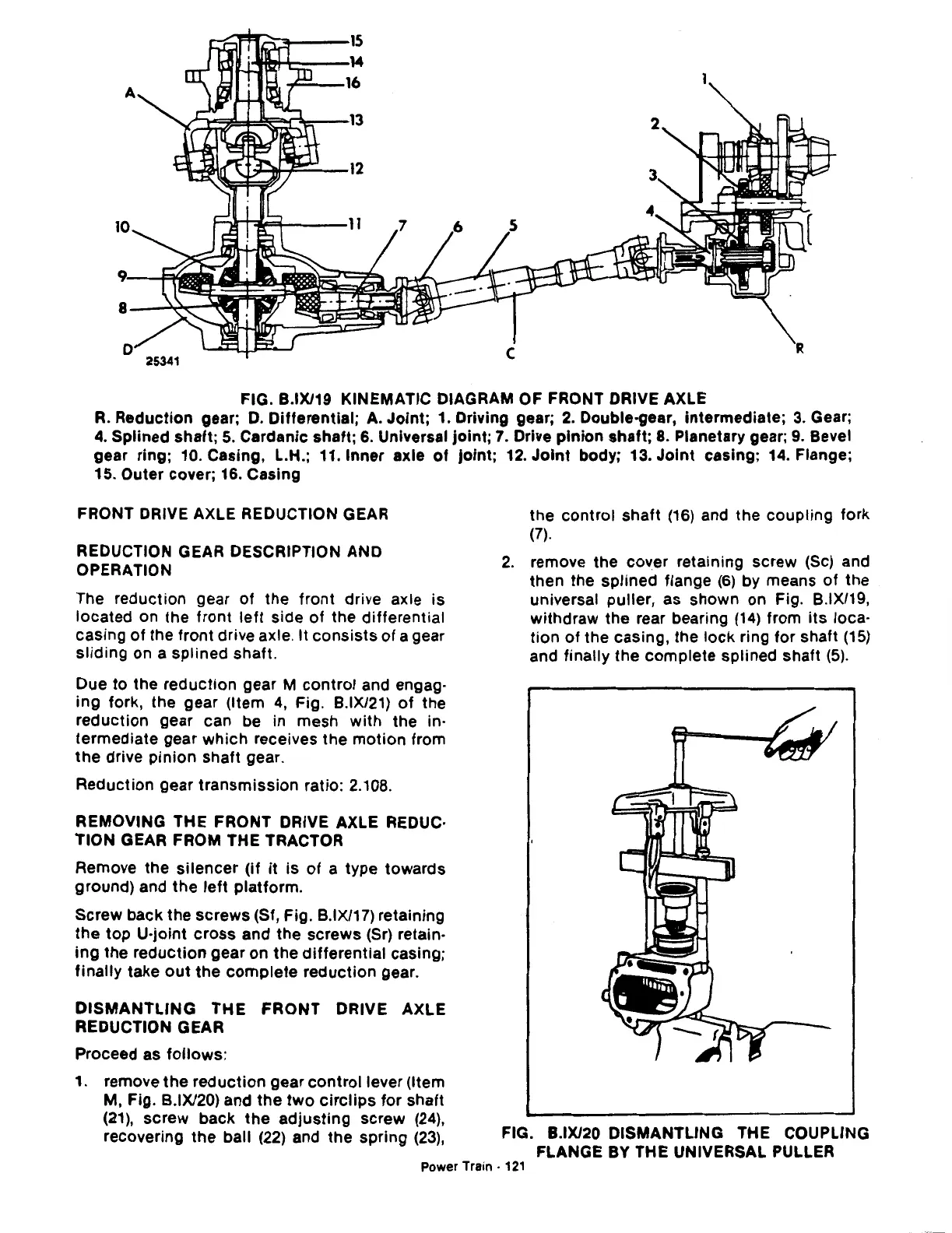
FIG. B.IX/19 KINEMATIC DIAGRAM OF FRONT DRIVE AXLE
R.
Reduction gear;
D.
Differential;
A.
Joint; 1. Driving gear;
2.
Double-gear, intermediate;
3.
Gear;
4.
Splined shaft;
5.
Cardanic shaft;
6.
Universal
joint;
7.
Drive pinion shaft;
8.
Planetary gear;
9.
Bevel
gear ring; 10. Casing, L.H.; 11. Inner axle
of
joint;
12.
Joint
body; 13.
Joint
casing;
14.
Flange;
15. Outer cover;
16.
Casing
FRONT DRIVE AXLE REDUCTION GEAR
REDUCTION GEAR DESCRIPTION AND
OPERATION
The reduction gear of the front drive axle is
located on the front
left
side of the differential
casing
of
the front drive axle. It consists of a gear
sliding on a splined shaft.
Due
to
the reduction gear M control and engag-
ing fork, the gear (Item
4,
Fig. B.IX/21)
of
the
reduction gear can be in mesh with the in-
termediate gear which receives the motion from
the drive pinion shaft gear.
Reduction gear transmission ratio: 2.108.
REMOVING THE FRONT DRIVE AXLE REDUC·
TION GEAR FROM THE TRACTOR
Remove the silencer (if
it
is
of
a type towards
ground) and the
left
platform.
Screw back the screws (Sf, Fig. B.IX/17) retaining
the
top U·joint cross and the screws
(Sr)
retain-
ing the reduction gear
on
the differential casing;
finally take
out
the
complete
reduction gear.
DISMANTLING
THE FRONT DRIVE AXLE
REDUCTION GEAR
Proceed as follows:
1. remove the reduction gear control lever (Item
M, Fig. B.IX/20) and the
two
circlips
for shaft
(21),
screw back the adjusting screw
(24),
recovering the ball
(22)
and the spring
(23),
the control shaft
(16)
and the coupling fork
(7).
2.
remove the cover retaining screw (Sc) and
then the splined flange
(6)
by means of the
universal puller, as shown on Fig. B.IX/19,
withdraw the rear bearing
(14)
from its loca-
tion
of the casing, the lock ring for shaft
(15)
and finally the complete splined shaft
(5).
FIG. B.IX/20 DISMANTLING THE COUPLING
FLANGE BY THE UNIVERSAL PULLER
Power Train ·
121
 Loading...

