25033
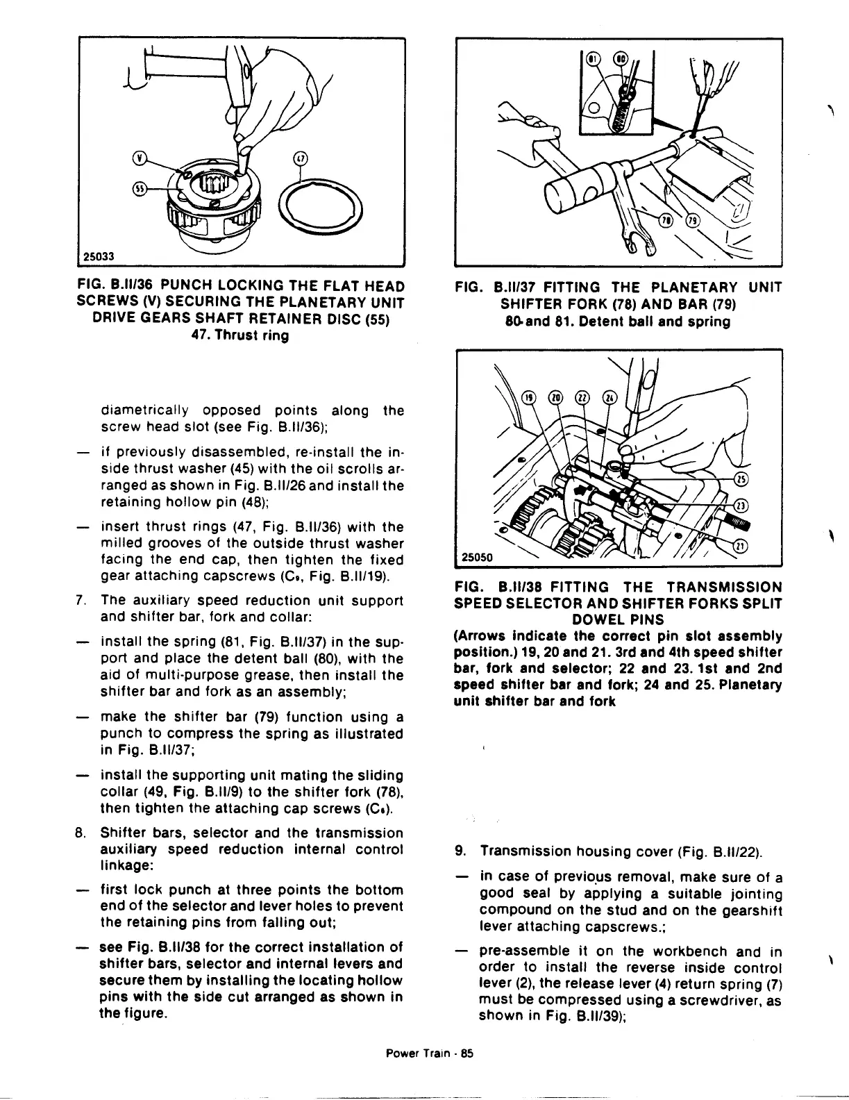
FIG.
8.11/36
PUNCH LOCKING THE FLAT HEAD
SCREWS
(V)
SECURING THE PLANETARY UNIT
DRIVE GEARS SHAFT RETAINER DISC (55)
47.
Thrust ring
diametrically opposed
points
along the
screw head slot (see Fig.
8.11136);
if
previously disassembled, re-install the in-
side thrust washer
(45)
with
the
oil
scrolls
ar-
ranged
as
shown in Fig. B.ll/26 and install the
retaining
hollow
pin
(48);
insert thrust rings
(47,
Fig. B.ll/36)
with
the
milled
grooves of the
outside
thrust
washer
facing the end cap, then
tighten
the fixed
gear attaching capscrews
(Ca, Fig. B.ll/19).
7.
The auxiliary speed reduction
unit
support
and
shifter
bar, fork and collar:
install the spring
(81,
Fig. B.ll/37) in the sup-
port and place the detent ball
(80),
with
the
aid
of
multi-purpose grease, then install
the
shifter
bar and fork as an assembly;
make the
shifter
bar
(79)
function
using a
punch to compress the spring as illustrated
in Fig. B.ll/37;
install the supporting
unit
mating
the
sliding
collar
(49,
Fig. B.ll/9)
to
the
shifter
fork
(78),
then
tighten
the attaching cap screws (Ce).
8.
Shifter
bars,
selector
and the transmission
auxiliary speed reduction internal
control
linkage:
first
lock
punch at three
points
the
bottom
end
of
the selector and lever holes
to
prevent
the retaining pins from falling out;
see Fig. B.ll/38
for
the
correct
installation
of
shifter
bars,
selector
and internal levers and
secure them by
installing
the
locating
hollow
pins
with
the
side
cut
arranged as
shown
in
the
figure.
FIG.
8.11137
FITTING THE PLANETARY UNIT
SHIFTER FORK
(78)
AND BAR
(79)
80.and 81. Detent ball and spring
FIG.
8.11/38
FITTING THE TRANSMISSION
SPEED SELECTOR AND SHIFTER FORKS SPLIT
DOWEL PINS
(Arrows Indicate the
correct
pin
slot
assembly
position.) 19,20 and
21.
3rd and 4th speed
shifter
bar, fork and selector;
22
and
23.
1st and 2nd
speed
shifter
bar and fork;
24
and 25. Planetary
unit
shifter
bar and fork
9.
Transmission
housing
cover (Fig. B.ll/22).
in case
of
previo.us removal, make sure
of
a
good seat by applying a suitable
jointing
compound
on the
stud
and on
the
gearshift
lever attaching capscrews.;
pre-assemble
it
on the workbench and in
order to install the reverse inside
control
lever
(2),
the release lever
(4)
return spring
(7)
must
be compressed using a screwdriver, as
shown in Fig.
8.11139);
Power Train · 85
'
\
 Loading...

