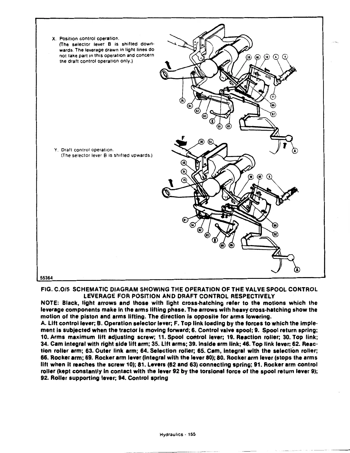
X.
Position
control
operation.
55364
(The
selector
lever B
is
shifted
down·
wards. The leverage
drawn
in
light
lines
do
not
take part in
this
operation and
concern
the draft
control
operation
only.)
Y.
Draf1
con1rol opera1ion.
(The selec1or lever B is shif1ed upwards.)
FIG. C.0/5 SCHEMATIC DIAGRAM SHOWING THE OPERATION OF THE VALVE SPOOL CONTROL
LEVERAGE
FOR
POSITION AND DRAFT CONTROL RESPECTIVELY
NOTE: Black,
light
arrows and those with
light
cross-hatching refer
to
the
motions
which the
leverage components make In the arms
lifting
phase. The arrows with heavy cross·hatching show the
motion
of
the piston and arms
lifting.
The direction Is opposite for arms lowering.
A.
Lift
control lever;
B.
Operation selector lever;
F.
Top
link
loading by the forces
to
which the imple·
ment
is
subjected when the tractor Is moving forward;
6.
Control valve spool;
9.
Spool return spring;
10. Arms maximum
lift
adjusting screw; 11. Spool
control
lever; 19. Reaction roller;
30.
Top
link;
34.
Cam Integral
with
right side
lift
arm;
35.
Lift
arms;
39.
Inside arm
link;
46.
Top
link
lever;
62.
Reac·
tion
roller arm; 63. Outer
link
arm; 64. Selection roller; 65. Cam, Integral with the selection roller;
66.
Rocker arm;
69.
Rocker arm lever (Integral
with
the lever
80);
80.
Rocker arm lever (stops the arms
lift
when It reaches the screw
10);
81.
Levers
(62
and
63)
connecting spring; 91. Rocker arm control
roller (kept constantly In contact with the lever
92
by
the torsional force
of
the spool return lever
9);
92.
Roller supporting lever;
94.
Control spring
Hydraulics·
155
 Loading...

