X
55391
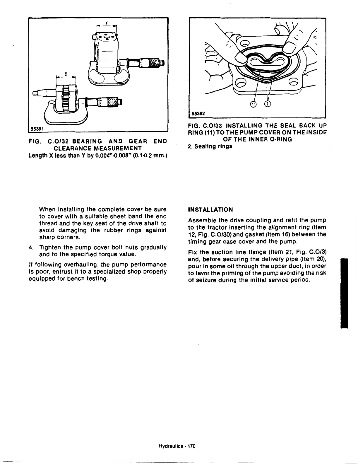
FIG.
C.0/32
BEARING
AND
GEAR
END
CLEARANCE MEASUREMENT
Length X less than Y by 0.004"·0.008" (0.1·0.2 mm.)
When
installing
the
complete
cover be sure
to
cover
with
a suitable sheet band the end
thread and the key seat of the drive shaft
to
avoid damaging
the
rubber
rings
against
sharp corners.
4.
Tighten
the
pump cover
bolt
nuts
gradually
and
to
the specified torque value.
If
following
overhauling, the
pump
performance
is
poor,
entrust
it
to
a specialized shop properly
equipped
for
bench
testing.
55392
FIG. C.0/33 INSTALLING THE SEAL BACK
UP
RING
(11)
TO THE PUMP COVER ON THE INSIDE
OF
THE INNER O·RING
2.
Sealing
rings
INSTALLATION
Assemble
the
drive
coupling
and
refit
the pump
to
the
tractor
inserting
the
alignment ring (Item
12, Fig. C.0/30) and gasket (Item 16) between the
timing
gear case cover and the pump.
Fix
the
suction
line
flange (Item 21, Fig. C.0/3)
and, before
securing
the
delivery pipe (Item
20),
pour
in
some
oil
through
the upper duct, in order
to
favor
the
priming
of
the
pump avoiding the risk
of
seizure
during
the
initial
service period.
Hydraulics·
170
 Loading...

