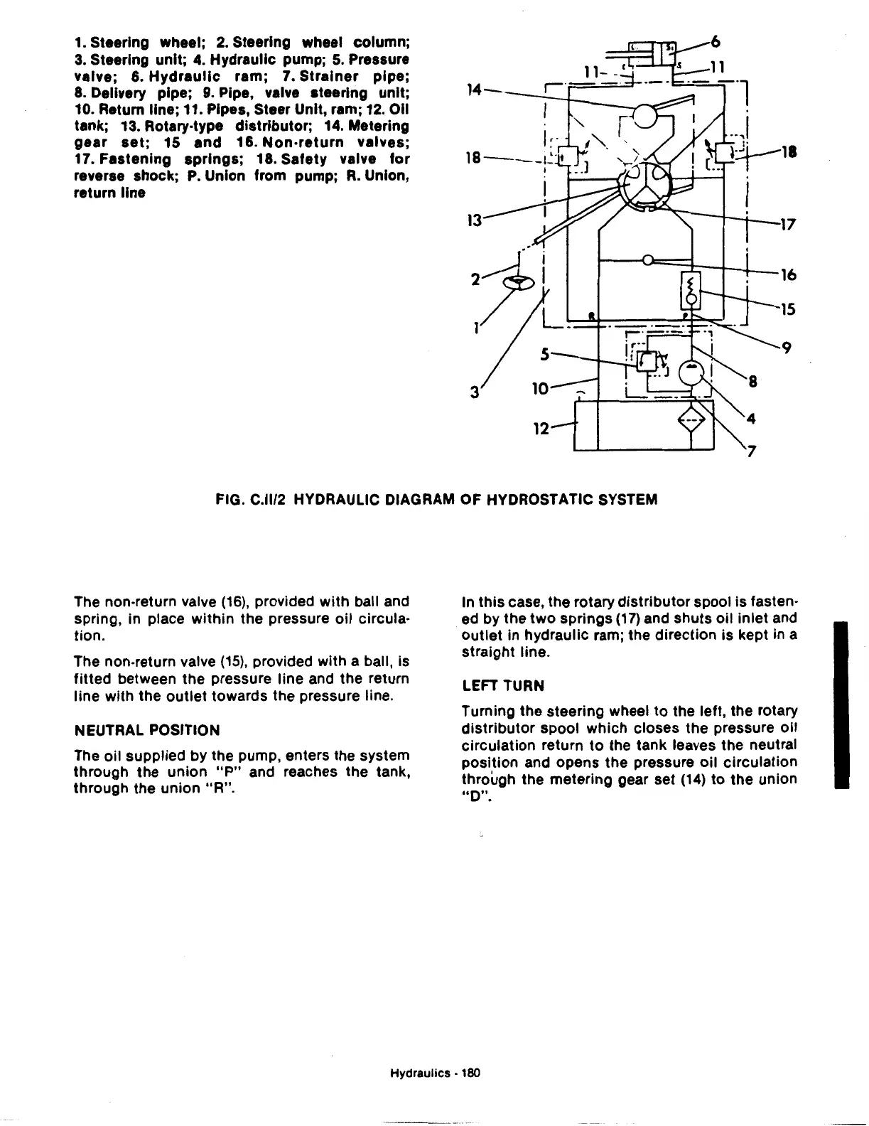
1.
Steering wheel;
2.
Steering wheel column;
3.
Steering unit;
4.
Hydraulic pump;
5.
Pressure
valve; 6.
Hydraulic
ram; 7.
Strainer
pipe;
8.
Delivery pipe;
9.
Pipe, valve steering unit;
10. Return line; 11. Pipes, Steer Unit, ram; 12. Oil
tank; 13. Rotary-type distributor; 14. Metering
gear
set;
15
and
16.
Non-return
valves;
17. Fastening
springs;
18. Safety valve
tor
reverse shock;
P.
Union from pump;
R.
Union,
return line
11
14-
--;-+--~~--
-·l
13
3
12
.
.J
~:.t--18
~I
17
16
15
9
FIG. C.ll/2 HYDRAULIC DIAGRAM OF HYDROSTATIC SYSTEM
The non-return valve
(16),
provided with ball and
spring, in place within the pressure oil circula-
tion.
The non-return valve
(15),
provided with a ball, is
fitted between the pressure line and the return
line with the
outlet
towards the pressure line.
NEUTRAL POSITION
The oil supplied by the pump, enters the system
through the union
"P"
and reaches the tank,
through the union
"A".
In
this
case, the rotary distributor spool is fasten-
ed by the two springs
(17)
and shuts oil inlet and
outlet
in hydraulic ram; the direction is kept in a
straight line.
LEFT TURN
Turning the steering wheel
to
the left, the rotary
distributor spool which closes the pressure oil
circulation return
to
the tank leaves the neutral
position and opens the pressure oil circulation
through the metering gear set
(14)
to the union
uo".
Hydraulics
• 180
 Loading...

