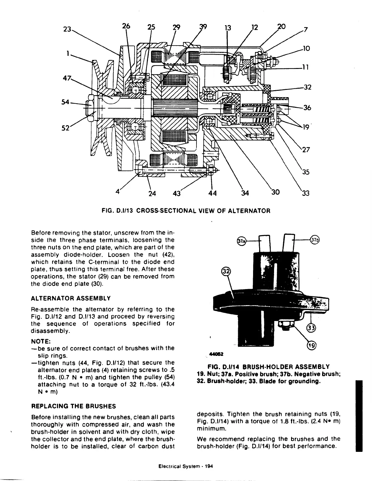
FIG. 0.1/13 CROSS-SECTIONAL VIEW
OF
ALTERNATOR
Before removing the stator, unscrew from the in·
side the three phase terminals, loosening the
three
nuts
on the end plate,
which
are part
of
the
assembly diode-holder. Loosen the
nut
(42),
which
retains the C-terminal
to
the
diode
end
plate,
thus
setting
this
terminal free. After these
operations, the
stator
(29)
can be removed from
the diode end plate
(30).
ALTERNATOR
ASSEMBLY
Re-assemble the alternator by referring
to
the
Fig.
0.1112
and
0.1113
and proceed by reversing
the
sequence
of
operations
specified
for
disassembly.
NOTE:
-be
sure
of
correct
contact
of
brushes
with
the
slip
rings.
-tighten
nuts
(44, Fig.
0.1112)
that secure
the
alternator
end plates
(4)
retaining screws
to
.5
ft.·lbs. (0.7 N • m) and
tighten
the
pulley
(54)
attaching
nut
to
a torque
of
32 ft.·lbs. (43.4
N •
m)
REPLACING
THE
BRUSHES
Before
installing
the new brushes, clean all parts
thoroughly
with
compressed air, and wash
the
brush-holder in solvent and
with
dry
cloth,
wipe
the
collector
and the end plate, where the brush·
holder
is
to
be installed, clear
of
carbon
dust
FIG. 0.1/14 BRUSH-HOLDER ASSEMBLY
19. Nut; 37a. Positive brush; 37b. Negative brush;
32.
Brush-holder; 33. Blade
for
grounding.
deposits.
Tighten
the
brush retaining
nuts
(19,
Fig.
0.1114)
with
a torque
of
1.8 ft.·lbs. (2.4
N•
m)
minimum.
We recommend replacing
the
brushes and the
brush-holder (Fig.
0.1114)
for
best performance.
Electrical
System·
194
 Loading...

