rotating the armature slowly. The ammeter will in-
dicate the
flow
of
a current, which
will
attain a
given magnitude at a certain distance
of
the blade
coupler
with
respect
to
the starting position. By
repeating
this
operation for each successive pair
of
bars, the ammeter reading, always in the chosen
position, shall always be the same.
No
flow
of
cur-
rent will be shown by the ammeter
if
the circuit is
interrupted. Should the ammeter readings differ,
the
cause may be shorts in the winding zones; in
this
case repeat at the shorting test
the
operations
indicated in the preceding paragraph.
~
..
• • •
~
-~
FIG. D.lll9 CHECKING FOR SHORT CIRCUITS
ACROSS THE ARMATURE WINDING
CONDUCTORS
(Any short
is
Indicated
by
vibration
of
steel blade
placed on the armature as shown in the figure.)
INDUCTION FIELDS
Testing
of
induction fields is necessary
to
check
the
insulation
to
ground (with respect
to
the hous-
ing and pole shoes on
which
they are arranged)
and the absence
of
broken-off
coils
(continuity
test).
Check by inserting the field windings on
an
a.c.
current, at rated voltage and with a test lamp con-
nected in series.
To check insulation
to
ground, put a tester in con-
tact with
the
housing and
the
other
with
the lead
of
the
winding
undergoing
testing.
The
presence
of
ground
is
shown
by
the
t~st
lamp
which
lights
up
(C, Fig.
0.11111).
Notice
that in many cases, the insulation defects
across the ground, are due
to
the presence
of
car-
bon
or
copper
dust
originated by brush and collec-
tor
wear and
which
can be easily removed by com-
pressed air.
To
check winding continuity,
put
the
testers In
contact
with
the leads
of
the winding undergoing
test. The test lamp
will
remain off,
if
the winding
is
open because
of
broken
or
dis-soldered connec-
tions.
Install insulation and weld the connections,
if
possible, but
do
not
attempt
repair
the
broken-off
winding
as
the
results
would
be
both
uneconomical and unreliable. In
this
case, replace
the
defective winding
with
a new and original one.
For this, remove the pole shoes by removal
of
the
screws.
Clean the housing by washing it in solvent and dry
it
with
compressed
air
so
to
remove all impurities;
the
pole shoes shall undergo the same procedure.
~.
·-.~~,~
~
,--
:-;
\·
....
._
..
44011
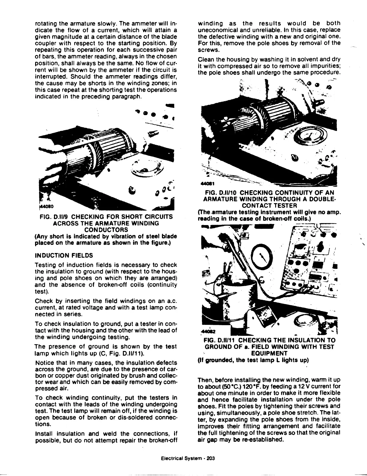
FIG. D.lll10 CHECKING CONTINUITY OF AN
ARMATURE WINDING THROUGH A DOUBLE·
CONTACT TESTER
(The .armature
testing
instrument
will
give
no
amp.
reading
in
the case
of
broken-off coils.)
-
ii?
~-
- -
--:---,.l~
._..
~-'
-.
I
-44CIIZ
FIG. D.ll/11 CHECKING THE INSULATION TO
GROUND
OF
a.
FIELD WINDING WITH TEST
EQUIPMENT
(If
grounded,
the
test
lamp
L
lights
up)
Then, before installing
the
new
winding, warm
it
up
to
about
(SO•C.)
120•F.
by
feeding a 12 V current for
about one
minute
in order
to
make
it
more flexible
and hence facilitate installation under the pole
shoes.
Fit
the poles by tightening their screws and
using, simultaneously, a pole shoe stretch. The lat-
ter, by expanding the pole shoes from the inside,
Improves their
fitting
arrangement and facilitate
the
full tightening
of
the screws so that the original
air
gap may be re-established.
Electrical System -
203
 Loading...

