8.111
BEVEL GEAR
AND
DIFFERENTIAL
25277
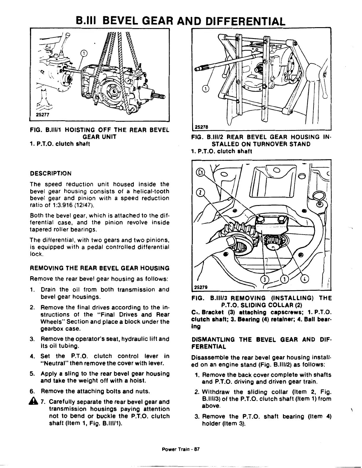
FIG. B.lll/1 HOISTING OFF THE REAR BEVEL
GEAR UNIT
1.
P.T.O.
clutch
shaft
DESCRIPTION
The speed reduction
unit
housed inside the
bevel gear housing
consists
of
a helical-tooth
bevel gear and pinion with a speed reduction
ratio of 1:3.916
(12/47).
Both the bevel gear, which is attached to the dif-
ferential case, and the pinion revolve inside
tapered roller bearings.
The differential, with
two
gears and
two
pinions,
is equipped
with
a pedal controlled differential
lock.
REMOVING THE
REAR
BEVEL GEAR HOUSING
Remove the rear bevel gear housing
as
follows:
1.
Drain the oil from both transmission and
bevel gear housings.
2.
Remove the final drives according
to
the in-
structions
of
the
"Final
Drives and Rear
Wheels" Section and place a
block
under the
gearbox case.
3.
Remove the operator's seat, hydraulic
lift
and
Its oil tubing.
4.
Set the P.T.O.
clutch
control
lever
in
"Neutral"
then remove the cover
with
lever.
5.
Apply a sling
to
the rear bevel gear housing
and take the weight
off
with
a hoist.
6.
Remove the attaching
bolts
and nuts.
A
7.
Carefully separate the rear bevel gear and
transmission housings paying
attention
not
to
bend
or
buckle the P.T.O.
clutch
shaft (Item
1,
Fig. B.lll/1
).
25278
FIG. B.lll/2
REAR
BEVEL GEAR HOUSING IN·
STALLED ON TURNOVER STAND
1. P.T.O.
clutch
shaft
FIG.
B.lll/3
REMOVING (INSTALLING) THE
P.T.O. SLIDING COLLAR
(2)
c,.
Bracket
(3)
attaching capscrews; 1. P.T.O.
clutch
shaft;
3.
Bearing (4) retainer; 4. Ball bear·
lng
DISMANTLING THE BEVEL GEAR AND DIF·
FERENTIAL
Disassemble the rear bevel gear housing install-
ed on an engine stand (Fig.
8.11112)
as follows:
1.
Remove the back cover
complete
with
shafts
and P.T.O. driving and driven gear train.
2.
Withdraw the
sliding
collar
(Item
2,
Fig.
8.111/3)
of
the P.T.O.
clutch
shaft (Item
1)
from
above.
3.
Remove the P.T.O.
shaft
bearing (Item
4)
holder (Item
3).
Power Train • 87
 Loading...

