5.
Cup shaped
plugs
(Item T, Fig. A.lll/4) seal
properly (test
with
oil
at 213
PSI
[15 kg/cm
2
]).
Should
the
test
show
defective
or
unreliable
sealing tightness, replace
the
plugs
and
repeat the
test
with
new
plugs
installed. If
necessary, grind all crankshaft journals
to
one
of
the undersizes
specified
in
"Fits
and
Tolerances" table. Make sure,
after
grinding,
to machine proper radii and
fillets
on jour-
nals and
to
chamfer the
lubrication
holes.
FRONT END SEAL INSTALLATION
Fluid
tightness
at
front
end
of
crankshaft is en-
sured by a rubber seal
with
coil
spring
which
is
force
fitted
in
the
timing
gear case cover. The
fundamental feature
of
this
seal
is
the spiral
rifling
of
the
sealing
lip
in the
direction
opposite
to
that
of
rotation
of
the
hub.
This
will
throw back
inside any
amount
of
fluid
which
the
hub
would
eventually tend
to
convey outside.
In case
of
oil leakage,
excluding
the
running-in
period during which parts may require adjust-
ment
of
their
final
position
of
assembly, remove
the
pulley hub (Fig. A.0/9A) and check:
1.
The working surface
of
the
seal for wear,
breakage
of
the
rifling
coil
or
of
the sealing
lip.
2.
The sealing surface in
contact
with
the
crankshaft
for
roughness or out-of-round ex-
ceeding 0.012 in. (0.3 mm.).
The seal cover
must
be removed
first
If
the
seal
is
to
be replaced. Take good
note
of
the
follow-
ing
points
to
avoid assembly trouble.
1.
Wipe
off
all traces
of
oil
and
dry
the
seal seat
In
the
cover thoroughly.
2.
Fit
the
seal In
its
seat
without
using
lubricants and apply a
uniform
pressure over
the
entire
seal ring by means
of
a seal In-
staller
so
that
the
seal
will
bottom
in
Its
seat.
3.
Lubricate
the
seal
lip
with
a
film
of
grease
or
thick
oil
to
avoid dry
contact
with
the
crankshaft surface at
the
start,
then
secure
the cover and
its
gasket
to
the
crankcase.
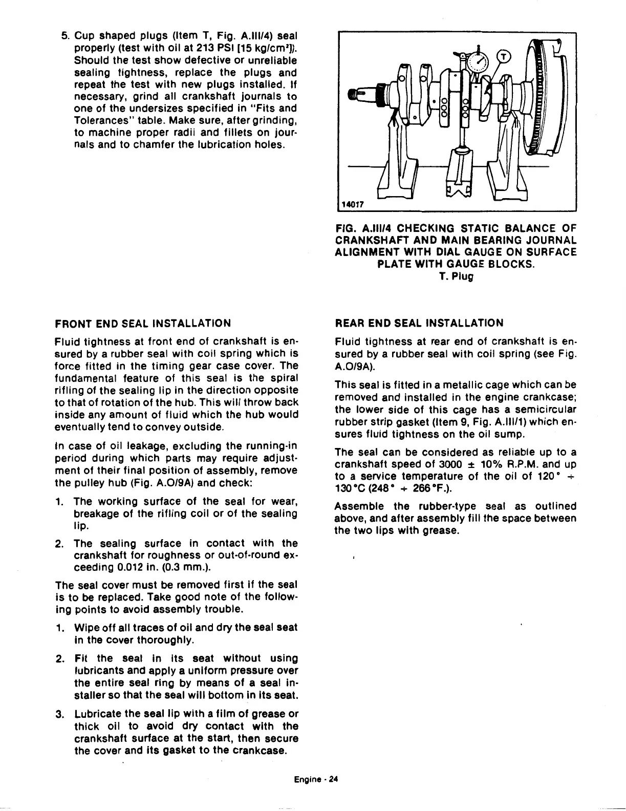
FIG. A.lll/4 CHECKING STATIC BALANCE
OF
CRANKSHAFT AND MAIN BEARING JOURNAL
ALIGNMENT WITH DIAL GAUGE
ON
SURFACE
PLATE WITH GAUGE BLOCKS.
T. Plug
REAR
END SEAL INSTALLATION
Fluid
tightness
at rear end
of
crankshaft is en-
sured by a rubber seal
with
coil spring (see Fig.
A.0/9A).
This seal is
fitted
in a
metallic
cage which can be
removed and installed in the engine crankcase;
the
lower
side
of
this
cage has a semicircular
rubber
strip
gasket (Item 9, Fig. A.lll/1) which en-
sures
fluid
tightness
on
the
oil sump.
The seal
can be considered as reliable up
to
a
crankshaft speed
of
3000
::1:
10% R.P.M. and up
to
a service temperature
of
the
oil
of
120 • +
130 ·c (248 • + 266 ·F.).
Assemble
the
rubber-type seal as
outlined
above, and
after
assembly
fill
the
space between
the
two
lips
with
grease.
Engine-
24
 Loading...

