A.ll VALVES AND TIMING MECHANISM
GENERAL
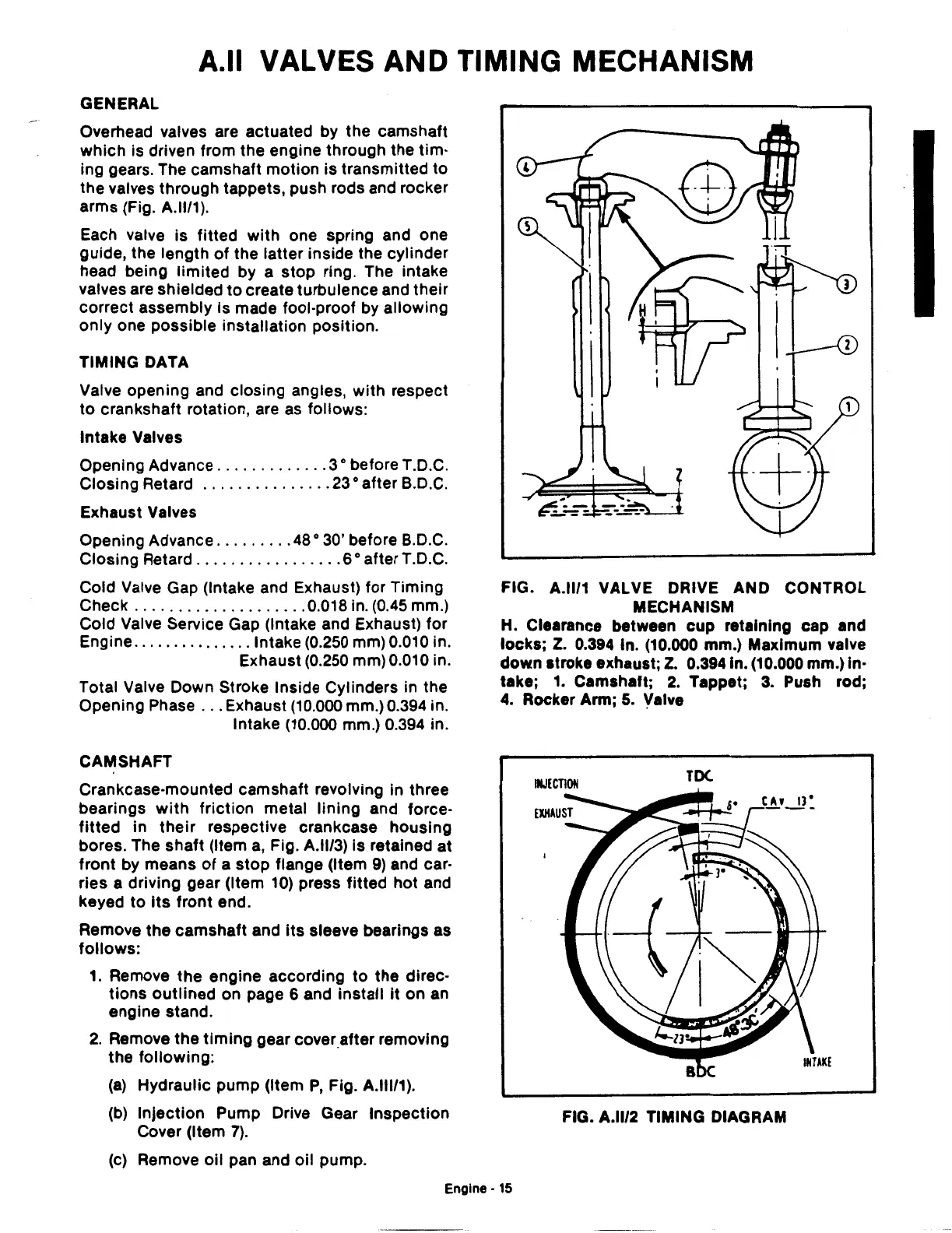
Overhead valves are actuated by the camshaft
which
is
driven from the engine through the
tim·
ing gears. The camshaft motion
is
transmitted
to
the valves through tappets, push rods and rocker
arms (Fig. A.ll/1).
Each valve is fitted
with
one spring and one
guide, the length
of
the latter inside the cylinder
head being limited by a stop ring. The intake
valves are shielded
to
create turbulence and their
correct assembly is made fool-proof by allowing
only one possible installation position.
TIMING DATA
Valve opening and closing angles, with respect
to
crankshaft rotation, are
as
follows:
Intake Valves
Opening Advance
.............
3 o before T.D.C.
Closing Retard
...............
23
o after B.D.C.
Exhaust Valves
Opening Advance
.........
48
o 30' before
B.
D.C.
Closing Retard
.................
6 o after T.D.C.
Cold Valve Gap (Intake and Exhaust) for Timing
Check
....................
0.018 in.
(0.45
mm.)
Cold Valve Service Gap (Intake and Exhaust) for
Engine
...............
Intake (0.250 mm) 0.010 in.
Exhaust (0.250 mm) 0.010 in.
Total Valve Down Stroke Inside Cylinders in the
Opening Phase
...
Exhaust (10.000 mm.) 0.394 in.
Intake (10.000 mm.) 0.394 in.
CAMSHAFT
Crankcase-mounted camshaft revolving in three
bearings
with
friction
metal
lining
and force-
fitted
in
their
respective crankcase housing
bores. The
shaft
(Item
a,
Fig. A.ll/3) Is retained
at
front
by means
of
a
stop
flange (Item
9)
and car-
ries a driving gear (Item
10)
press
fitted
hot
and
keyed
to
Its
front
end.
Remove the camshaft and
its
sleeve bearings as
follows:
1. Remove the engine according
to
the direc-
tions
outlined
on page 6 and install It on an
engine stand.
2.
Remove the
timing
gear
cover_
after removing
the following:
(a)
Hydraulic pump (Item
P,
Fig. A.lll/1).
(b) Injection Pump Drive Gear Inspection
Cover (Item
7).
(c) Remove
oil
pan and oil pump.
FIG. A.ll/1 VALVE DRIVE AND CONTROL
MECHANISM
H. Clearance between
cup
retaining cap and
locks;
Z.
0.394 ln. (10.000 mm.) Maximum valve
down
stroke exhaust;
Z.
0.3941n. (10.000 mm.) In·
take; 1. Camshaft;
2.
Tappet;
3.
Push rod;
4.
Rocker Arm;
5.
Valve
FIG. A.ll/2 TIMING DIAGRAM
Engine·
15
 Loading...

