FIG. A.IV/9 TIMING INDEX
~~~~~-
FOR
COR·
RECT
PUMP· ENGINE TIMING
INSTALLING INJECTION PUMP
(Read CAUTION and WARNING statements at
start
of
this
section.)
1.
Align
all
timing
marks (Fig. A.ll/13).
2.
Boltholes
on
injection
pump
mounting
are
slotted
for
adjustment
purposes. Desired
position
of
injection
pump is shown by
assembly marks on
pump
and timing-gear
case.
3.
Insert injection-pump shaft,
with
key and
lock
washer
into
its
location in injection-
pump
drive gear and thread cap screw in
drive gear on injection-pump shaft. Start cap
screws through hole in drive plate
of
injec·
tion
pump
into
holes in
timing
gear.
4.
Tighten
nut
on drive gear
to
60 ft.-lbs. Posi·
tion
assembly
marks, and
tighten
drive-plate
cap
screws
to
21
ft.-lbs.
5.
Fit
injection
pump drive-gear cover and
gasket
to
timing-gear cover.
6.
Attach
fuel
lines
between
injection
pump
and
second
filter,
tightening
to
10
ft.-lbs.
7.
Attach
control
linkage
to
throttle
arm (Item
36, Fig. A.IV/8) and governor shut-off lever
(32).
ADJUSTING IN.JECTION PUMP
1.
With
engine running at
low
idle and hand
thrott'e
at
minimum
setting,
check
reading
of
tachourmeter
on
instrument
panel.
If
crankshaft speed varies from 800 R.P.M., ad·
just
low-idle
adjustment
screw (Item
94,
Fig.
A.IV/7).
2.
With
engine
running at high idle, and hand
throttle
set at
maximum
position,
check
tachourmeter
reading.
If
crankshaft speed
varies from 2350 R.P.M.
(360);
2550 R.P.M.
(460
& 510),
adjust
to
proper
setting.
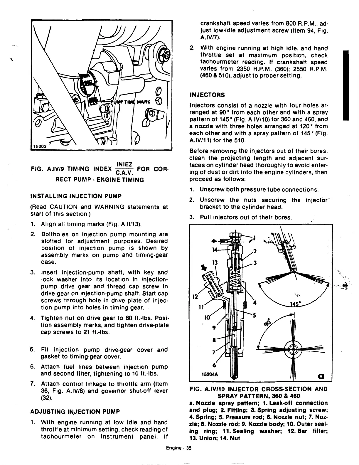
INJECTORS
Injectors
consist
of
a nozzle
with
four
holes ar·
ranged at 90 • from each
other
and
with
a spray
pattern
of
145 • (Fig. A.IV/10)
for
360 and 460, and
a nozzle
with
three holes arranged at 120 o from
each
other
and
with
a spray pattern
of
145 o (Fig.
A.IV/11)
for
the
510.
Before removing the
injectors
out
of
their
bores,
clean
the
projecting
length
and adjacent sur-
faces on
cylinder
head
thoroughly
to
avoid enter-
ing
of
dust
or
dirt
into
the engine cylinders, then
proceed as
follows:
1.
Unscrew
both
pressure
tube
connections.
2.
Unscrew the
nuts
securing the
injector"
bracket
to
the
cylinder
head.
3.
Pull
injectors
out
of
their
bores.
12
FIG. A.IV/10 INJECTOR CROSS-SECTION AND
SPRAY PATTERN,
360
&
460
a.
Nozzle spray pattern;
1.
Leak-off connection
and plug;
2.
Fitting;
3.
Spring adjusting screw;
4.
Spring;
5.
Pressure rod;
6.
Nozzle nut;
7.
Noz·
zle;
8.
Nozzle rod;
9.
Nozzle body; 10. Outer seal·
lng ring; 11. Sealing washer; 12. Bar filter;
13.
Union;
14.
Nut
Engine·
35
 Loading...

