5.
Withdraw the
lower
taper
roller
bearing (Item
7)
by hand.
6.
Remove
the
cup
of
the
lower
bearing (Item
7)
using a universal
puller
(Fig. B.VIII/2) and
recover
the
shims.
NOTE: The inner .races
of
both upper and lower
taper roller bearings are machined directly on
the body
of
the worm screw which, for service,
is furnished together with the steering shaft,
as an assembly.
In
case
of
replacement, remove the bushings (Items
10
and
11,
Fig. B.VIII/3) from the steering box and
from the side cover by means of a puller (Item
D,
Fig. B.VIII/3). Notice that the bushing (Item
11)
is to
be removed after the oil seal (Item
12).
INSPECTION
Check the worm and nut surfaces for nicks
or
seizure marks.
Make sure that the clearance between bushings and
nut shaft is within the permissible limits.
(See
"Fits
and Tolerances" table.)
Also make sure that the nut has no end play
because
of
worm nut thrust washers (Item
R,
Fig.
B.VIII/4). If so, replace the whole nut shaft as
an
assembly.
Try the worm screw roller bearings for free running
and check the oil seal (Item
12,
Fig. B.VIII/3) for effi-
ciency and reliability.
Check the steering levers and tie-rods
for
bends
of
bucklings,
and replace them
if
necessary.
ASSEMBLY
Assemble the steering box as follows:
1.
Insert the shim stack
(Items,,
Fig. B.VIII/4) and
install the cup
of
the lower taper roller bearing
(Item
7)
using a suitable driver.
85319
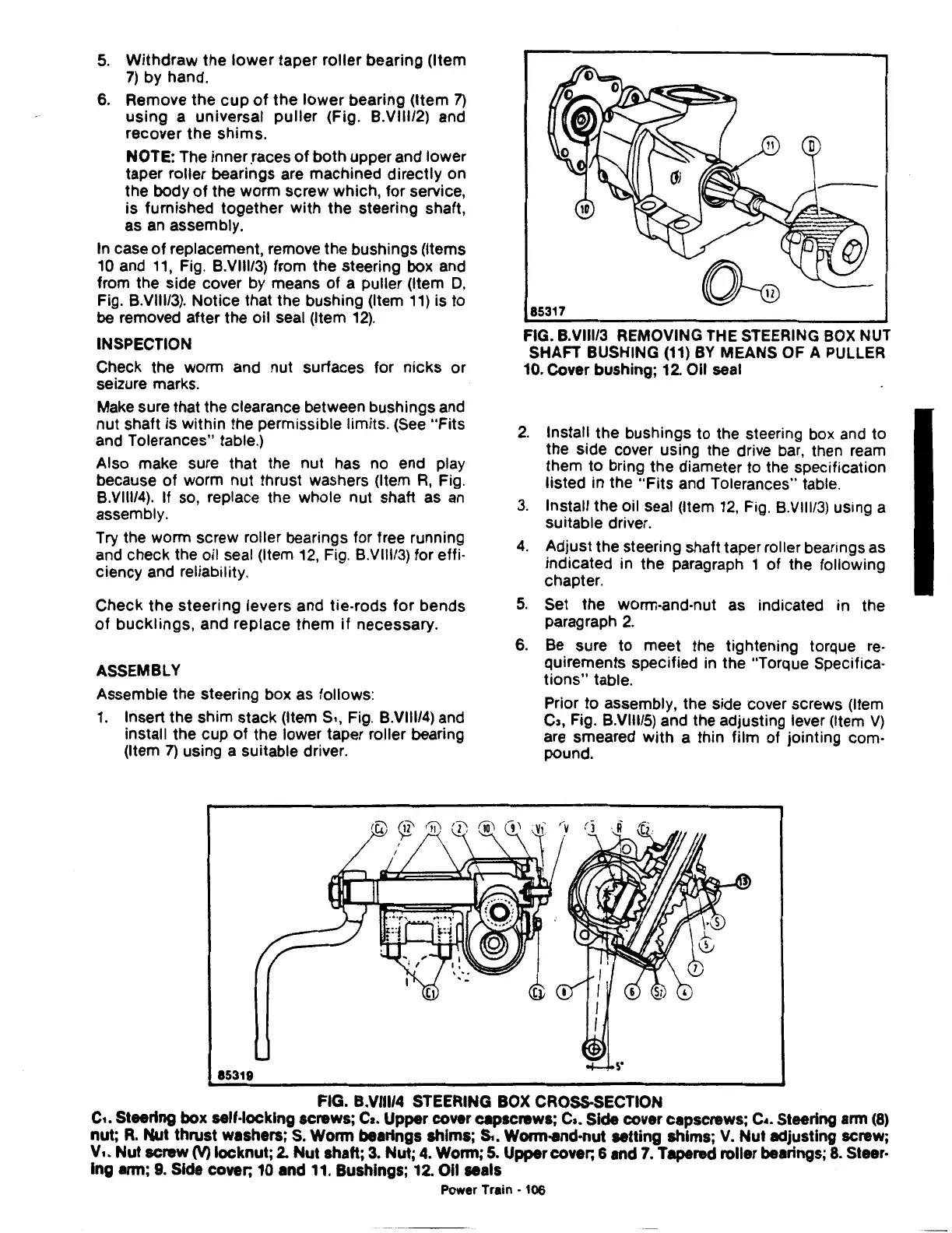
FIG. B.VIII/3 REMOVING THE STEERING
BOX
NUT
SHAFT BUSHING
(11)
BY
MEANS OF A PULLER
10.
Cover bushing;
12.
Oil seal
2.
Install the bushings
to
the steering box and to
the side cover using the drive
bar,
then
ream
them
to
bring the diameter to the specification
listed in the
"Fits
and Tolerances" table.
3.
Install the oil seal (Item
12,
Fig. B.VIII/3) using a
suitable driver.
4.
Adjust the steering shaft taper roller bearings as
indicated in the paragraph 1 of the following
chapter.
5.
Set the worm-and-nut as indicated in the
paragraph
2.
6.
Be
sure
to
meet the tightening torque
re-
quirements specified in the "Torque Specifica-
tions"
table.
Prior
to
assembly, the side cover screws (Item
c,,
Fig. B.VIII/5) and the adjusting lever (Item
V)
are smeared with a thin film of jointing com-
pound.
FIG. B.VIII/4 STEERING BOX CROSS.SECTION
c,.
Steering box self-locking screws;
Ca.
Upper cover capscrews;
Ca.
Side cover capscrews; c
•.
Steering arm
(8)
nut;
R.
Nut
thrust washers;
S.
Worm bearings shims;
S,.
Wonn-and-nut setting shims;
V.
Nut
adjusting screw;
v,.
Nut
screw (V) locknut;
2.
Nut
shaft;
3.
Nut;
4.
Worm;
5.
Upper cover;
&and
7.
Tapered roller bearings;
8.
Steer·
lng arm;
9.
Side cover; 10 and 11. Bushings; 12. Oil seals
Power
Train-
106
 Loading...

