25017
FIG.
B.ll/3
REMOVING
(INSTALLING)
THE
TRANSMISSION
3.
Disconnect
the
link
from the
clutch
control
outside
arm.
4.
Apply a
hoist
to
the
transmission
housing
and take the weight off.
A
5.
Place a hydraulic
jack
under the trans·
mission
housing, remove
attaching
nuts
and
bolts
and then the
transmission
unit
withdrawing
it
forward (Fig.
8.1113)
and
paying
attention
not
to
damage the P.T.O.
clutch
shaft.
DISMANTLING THE 6·SPEEO TRANSMISSION
In order
to
facilitate
disassembly we recommend
installing
the
transmission
unit on an
engine
stand.
Proceed then as
follows:
1.
Remove the
transmission
top
cover (Fig.
8.11/4)
complete:
The
clutch
release
collar
(Item
7,
Fig.
8.11/5)
after
disconnecting
the
grease line (Item
18)
from
the
housing.
Remove
the
shifter
fork
(Item 21) and
shaft
(Item
36)
after
removing the
capscrew
(Item
Cu).
2.
Remove
the
attaching
capscrews
(Item
Cs,
Fig. B.ll/5) and
withdraw
the
clutch
shaft
(Item
24,
Fig.
8.11/7)
and
support
together
with
the
clutch-transmission
shaft
joint
(Item
G).
NOTE: Due
to
the
fit
of
the
nylon
housing
(Item
25,
Fig.
8.1117)
on the rear end
of
the
clutch
shaft, the
latter
may
come
off
together
with
the shaft.
3.
Remove the
two
front bearing washers
for
driving and driven
shafts
using a puller,
with
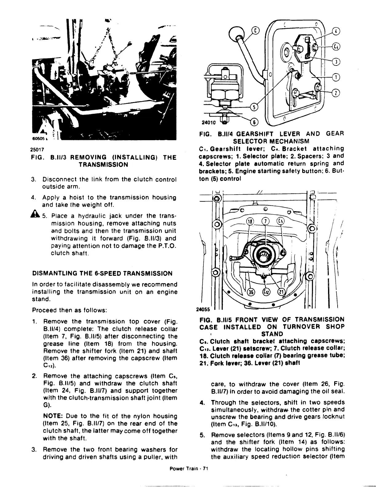
FIG. B.ll/4 GEARSHIFT LEVER AND GEAR
SELECTOR MECHANISM
c,.
Gearshift
lever;
c
•.
Bracket
attaching
capscrews; 1.
Selector
plate;
2.
Spacers; 3 and
4. Selector plate
automatic
return spring and
brackets;
5.
Engine
starting
safety
button;
6. But·
ton
(5)
control
R.i-.
It
1
' I
24055
FIG. B.ll/5 FRONT VIEW OF TRANSMISSION
CASE
INSTALLED
ON TURNOVER SHOP
STANO
Cs.
Clutch
shaft
bracket
attaching
capscrews;
Cu.
Lever (21) setscrew; 7.
Clutch
release collar;
18.
Clutch
release
collar
(7)
bearing grease tube;
21. Fork lever; 36. Lever (21)
shaft
care,
to
withdraw
the
cover (Item 26, Fig.
8.1117)
in order
to
avoid damaging
the
oil seal.
4.
Through
the
selectors,
shift
in
two
speeds
simultaneously,
withdraw
the
cotter
pin and
unscrew
the bearing and drive gears
locknut
(Item
Cu,
Fig.
8.11110).
5.
Remove selectors (Items 9 and 12, Fig.
8.11/6)
and the
shifter
fork (Item
14)
as
follows:
withdraw
the
locating
hollow
pins
shifting
the auxiliary speed reduction
selector
(Item
Power Train ·
71
 Loading...

