24
23
22
21
16-----$
'1---<1>
20
17
18
13
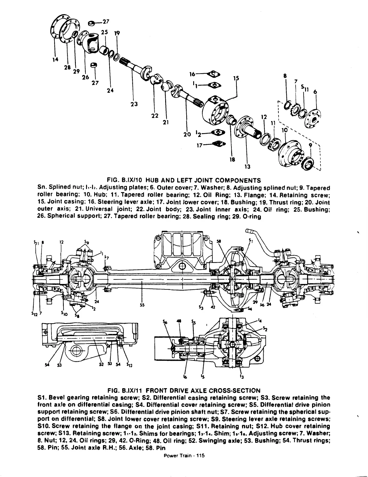
FIG. B.IX/10 HUB AND LEFT JOINT COMPONENTS
Sn. Splined nut; J,·b. Adjusting plates;
6.
Outer cover;
7.
Washer;
8.
Adjusting
splined nut;
9.
Tapered
roller bearing; 10. Hub; 11. Tapered roller bearing; 12. Oil Ring; 13. Flange; 14. Retaining screw;
15.
Joint
casing; 16. Steering lever axle; 17.
Joint
lower cover; 18. Bushing; 19. Thrust ring;
20.
Joint
outer axis;
21.
Universal
joint;
22.
Joint
body;
23.
Joint
Inner axis;
24.
Oil ring;
25.
Bushing;
26.
Spherical support;
27.
Tapered roller bearing;
28.
Sealing ring;
29.
O·ring
ss
FIG. B.IX/11 FRONT DRIVE AXLE CROSS·SECTION
S1.
Bevel gearing retaining screw; S2. Differential casing retaining screw;
S3.
Screw retaining the
front
axle on differential casing;
S4.
Differential cover retaining screw;
SS.
Differential drive
pinion
support retaining screw;
S6.
Differential drive
pinion
shaft
nut;
S7.
Screw retaining the spherical sup·
port
on
differential;
S8.
Joint
lower
cover retaining screw;
S9.
Steering lever axle retaining screws;
S10. Screw retaining the flange
on
the
joint
casing; S11. Retaining
nut;
S12.
Hub
cover retaining
screw;
S13.
Retaining screw; 1,.12. Shims
for
bearings; 1,.1
••
Shim; h·1a.
Adjusting
screw;
7.
Washer;
8.
Nut; 12, 24. Oil rings; 29,
42.
O·Ring;
48.
Oil ring;
52.
Swinging
axle; 53. Bushing;
54.
Thrust rings;
58.
Pin;
55.
Joint
axle R.H.;
56.
Axle; 58. Pin
Power
Train-
115
'
 Loading...

