55373
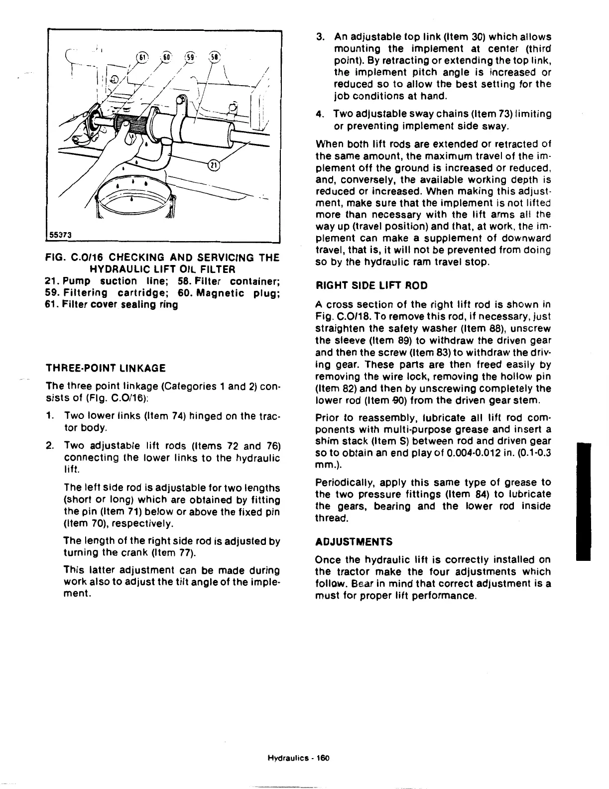
FIG. C.0/16 CHECKING AND SERVICING THE
HYDRAULIC LIFT OIL FILTER
21. Pump
suction
line;
58.
Filter
container;
59.
Filtering
cartridge;
60.
Magnetic
plug;
61. Filter cover sealing ring
THREE-POINT LINKAGE
The three point linkage (Categories 1 and
2)
con·
sists
of
(Fig. C.0/16):
1.
Two
lower
links
(Item
74)
hinged on the trac·
tor
body.
2.
Two adjustable
lift
rods (Items
72
and
76)
connecting
the lower links
to
the hydraulic
lift.
The
left
side rod is adjustable for
two
lengths
(short
or
long)
which
are obtained by
fitting
the
pin
(Item
71)
below or above the fixed pin
(Item
70),
respectively.
The length
of
the right side rod is adjusted by
turning
the crank (Item
77).
This latter
adjustment
can be made during
work also
to
adjust
the
tilt
angle
of
the imple·
ment.
3.
An adjustable
top
link
(Item
30)
which allows
mounting
the
implement
at center (third
point). By retracting
or
extending
the top link,
the
implement
pitch
angle
is
increased or
reduced
so
to
allow
the
best
setting
for
the
job
conditions
at hand.
4.
Two adjustable sway
chains
(Item
73)
limiting
or preventing
implement
side sway.
When both
lift
rods are extended
or
retracted
of
the
same amount, the
maximum
travel
of
the im·
plement
off
the ground is increased or reduced,
and, conversely,
the
available working depth is
reduced
or
increased. When making
this
adjust·
ment, make sure
that
the
implement
is not lifted
more than necessary
with
the
lift
arms all the
way up (travel
position)
and that, at work, the im·
plement can make a
supplement
of
downward
travel, that is,
it
will
not
be prevented from doing
so by the hydraulic ram travel stop.
RIGHT SIDE
LIFT
ROD
A cross
section
of
the
right
lift
rod is shown in
Fig. C.0/18. To remove
this
rod,
if
necessary,
just
straighten
the
safety washer (Item
88),
unscrew
the
sleeve (Item
89)
to
withdraw
the
driven gear
and then the screw (Item
83)
to
withdraw
the driv·
ing gear. These parts are then freed easily by
removing the wire lock, removing
the
hollow pin
(Item
82)
and then by
unscrewing
completely
the
lower
rod (Item
.go)
from
the
driven gear stem.
Prior to reassembly, lubricate
all
lift
rod com·
ponents
with
multi-purpose grease and insert a
shim
stack
(Item S) between rod and driven gear
so
to
obtain an end play
of
0.004·0.012 in. (0.1·0.3
mm.).
Periodically, apply
this
same type
of
grease
to
the
two
pressure
fittings
(Item
84)
to
lubricate
the
gears, bearing and
the
lower
rod inside
thread.
ADJUSTMENTS
Once the hydraulic
lift
is
correctly
installed on
the
tractor
make
the
four
adjustments
which
follow.
Bear in
mind
that
correct
adjustment
is a
must
for proper
lift
performance.
Hydraulics
· 160
 Loading...

