'
14009
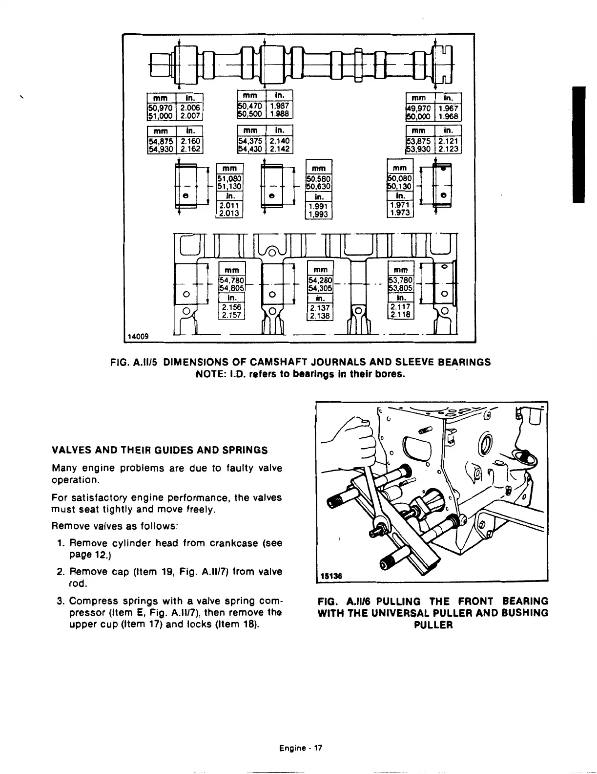
mm
50,970
51,000
mm
54,875
54,930
mm
54,375
~·(430
ln.
2.140
2.142
2.121
2.123
FIG. A.ll/5 DIMENSIONS
OF
CAMSHAFT JOURNALS AND SLEEVE BEARINGS
NOTE: I.D. refers
to
bearings In
their
bores. ·
VALVES AND THEIR GUIDES AND SPRINGS
Many engine problems are due
to
faulty valve
operation.
For satisfactory engine performance, the valves
must
seat
tightly
and move freely.
Remove valves
as
follows:
1.
Remove cylinder head from crankcase (see
page
12.)
2.
Remove cap (Item
19,
Fig. A.ll/7) from valve
rod.
3.
Compress springs
with
a valve spring com-
pressor (Item
E,
Fig. A.ll/7), then remove the
upper cup (Item
17)
and locks (Item
18).
FIG. A.ll/6 PULLING THE FRONT BEARING
WITH THE UNIVERSAL PULLER AND BUSHING
PULLER
Engine·
17
 Loading...

