FIG. B.l/17 CROSS SECTION OF THE 11"
CLUTCH
A.
0.098 in.
(2.5
mm) gap between sliding sleeve
(12)
and throw
out
lever
(14);
B.
0.098 in. (2.5 mm)
gap between sleeve
(1
0)
and throw
out
lever (9);
CJ
and c
•.
cap screws securing
clutch
housing
to
engine block; Cu. cap screw,
clutch
fork;
1.
P.T.O.
clutch
disc;
2.
P.T.O.
clutch
thrust
plate;
3.
Flexible
disc;
4.
Clutch housing;
5.
Push rod;
6.
Main
clutch
disc; 7. Main
clutch
thrust
plate;
9. P.T.O.
clutch
lever; 10. P.T.O.
clutch
sliding
sleeve; 11. P.T.O. throw
out
fork; 12. Main
clutch
sliding
sleeve; 13. Main
clutch
throw
out
fork;
14. Main
clutch
lever; 15. Push rod; 16. Return
spring; 17. Bearing P.T.O. shaft.
and
7) as illustrated to make sure the parts are re·
assembled in
their
respective original
positions
thus
maintaining the dynamic balance
of
the unit
as set at
the
factory.
Clutches
can be disassembled
without
using any
specialized
tooling,
as follows:
gradually cross-loosen the nuts
(8,
Fig.
8.1/15)
and then remove the P.T.O. clutch
pressure plate
(2)
and the dished spring
(3,
Fig.
8.1112).
remove
the
pressure plate (7)
with
adjusting
screws
(19)
and transmission disc
(6);
remove the
split
pins
(22,
Fig.
8.1/16)
and
remove the pins
(21)
to
remove the transmis-
sion
clutch
release levers
(14)
with push rods
and P.T.O. release levers
(9),
with
rods attach-
ed.
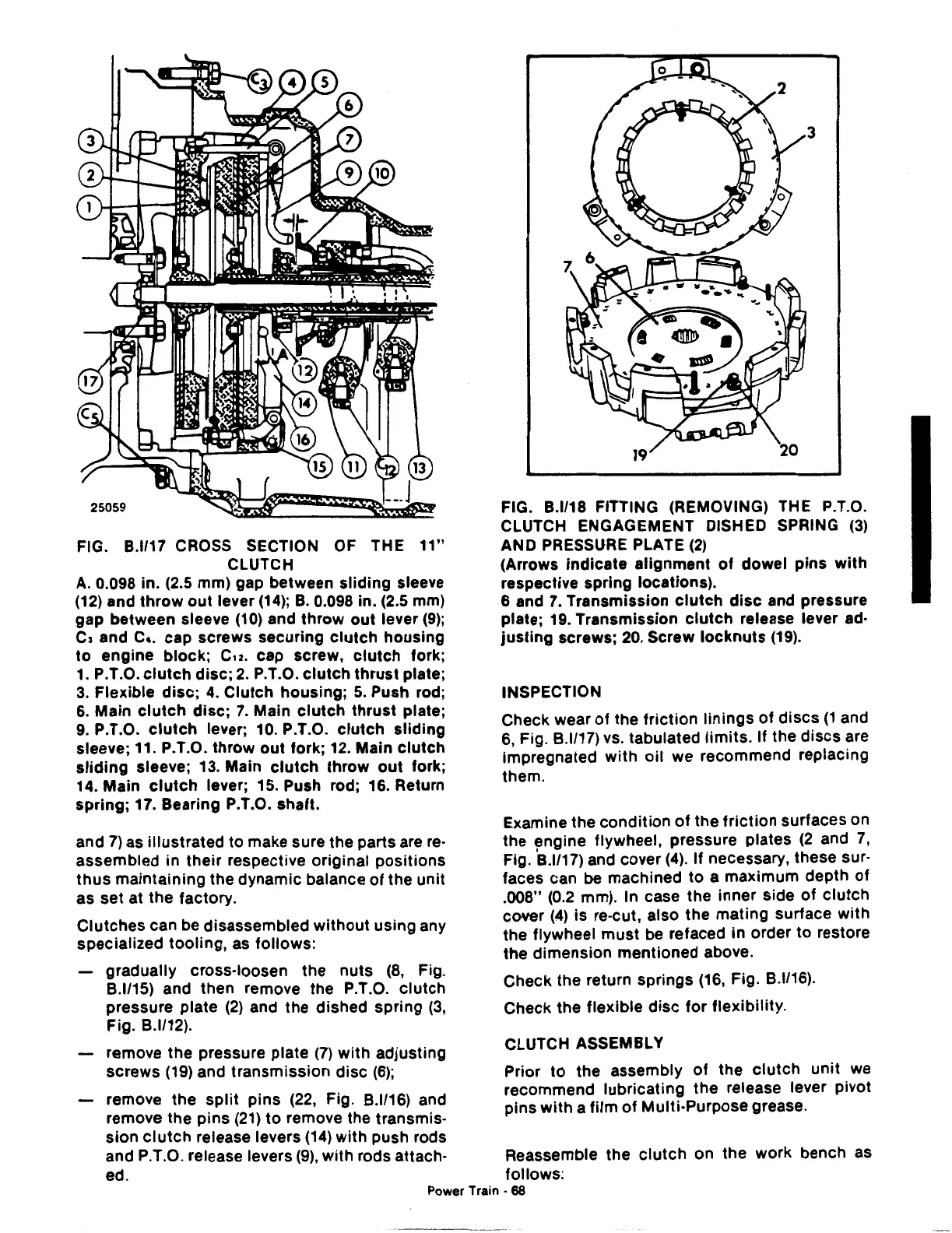
FIG. B.l/18 FITTING (REMOVING) THE P.T.O.
CLUTCH ENGAGEMENT DISHED SPRING
(3)
AND PRESSURE PLATE
(2)
(Arrows indicate alignment
of
dowel
pins
with
respective spring locations).
6 and
7.
Transmission
clutch
disc
and pressure
plate; 19. Transmission
clutch
release lever ad·
justing
screws;
20.
Screw
locknuts
(19).
INSPECTION
Check wear
of
the
friction
linings
of
discs
(1
and
6,
Fig.
8.1117)
vs. tabulated
limits.
If
the
discs
are
impregnated
with
oil we recommend replacing
them.
Examine the condition
of
the
friction
surfaces on
the engine flywheel, pressure plates
(2
and
7,
Fig.
'8.1117)
and cover
(4).
If necessary, these sur-
faces can
be machined
to
a maximum depth
of
.008"
(0.2
mm). In case the inner side
of
clutch
cover
(4)
is re-cut, also
the
mating surface
with
the flywheel
must
be refaced in order to restore
the dimension mentioned above.
Check the return springs
(16,
Fig.
8.1116).
Check the flexible
disc
for
flexibility.
CLUTCH ASSEMBLY
Prior
to
the assembly
of
the
clutch
unit
we
recommend lubricating the release lever pivot
pins
with
a
film
of
Multi-Purpose grease.
Reassemble the
clutch
on the work bench as
follows:
Power Train • 68
 Loading...

