E
9
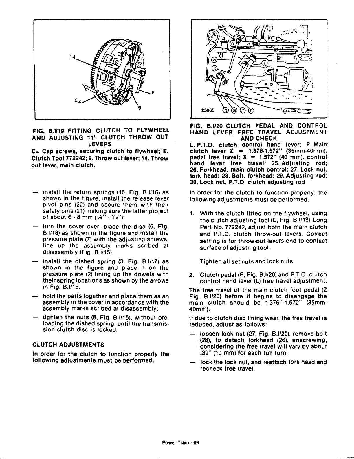
FIG.
8.1119
FITTING CLUTCH TO FLYWHEEL
AND ADJUSTING
11"
CLUTCH THROW OUT
LEVERS
c
•.
Cap screws,
securing
clutch
to
flywheel;
E.
Clutch
Tool772242;
9.
Throw
out
lever; 14.
Throw
out
lever,
main
clutch.
install the return springs
(16,
Fig.
8.1116)
as
shown in the figure, install the release lever
pivot
pins
(22)
and secure
them
with
their
safety pins
(21)
making sure the
latter
project
of
about 6 · 8 mm (1/4" ·
~/u");
turn the cover over, place the
disc
(6,
Fig.
8.1/18)
as shown in the figure and
install
the
pressure plate
(7)
with
the
adjusting
screws,
line up the assembly marks scribed at
disassembly (Fig.
8.1/15).
install the dished spring
(3,
Fig.
8.1117)
as
shown in the figure and place
it
on the
pressure plate
(2)
lining
up the
dowels
with
their
spring
locations
as shown by the arrows
in Fig.
8.1118.
hold the parts
together
and place them as an
assembly in the cover in accordance
with
the
assembly marks scribed at disassembly;
tighten
the
nuts
(8,
Fig.
8.1115),
without
pre-
loading the dished spring,
until
the
transmis-
sion
clutch
disc
is
locked.
CLUTCH ADJUSTMENTS
In
order
for
the
clutch
to
function
properly
the
following
adjustments
must
be performed.
FIG.
8.1120
CLUTCH PEDAL AND CONTROL
HAND
LEVER FREE TRAVEL ADJUSTMENT
AND CHECK
L. P.T.O.
clutch
control
hand lever;
P.
Main·
clutch
lever Z = 1.376-1.572" (35mm-40mm).
pedal free travel; X
= 1.572"
(40
mm).
control
hand
lever
free travel; 25.
Adjusting
rod;
26. Forkhead,
main
clutch
control;
27. Lock nut,
fork
head; 28.
Bolt,
forkhead;
29.
Adjusting
rod;
30.
Lock
nut,
P.T.O.
clutch
adjusting
rod
In
order
for
the
clutch
to
function
properly, the
following
adjustments
must
be performed.
1.
With
the
clutch
fitted
on the flywheel,
using
the
clutch
adjusting
tool
(E,
Fig.
8.1/19),
Long
Part No. 772242,
adjust
both
the main
clutch
and P.T.O.
clutch
throw-out levers. Correct
setting
is
for
throw-out
levers end
to
contact
surface
of
adjusting
tool.
Tighten
all set
nuts
and
lock
nuts.
2.
Clutch
pedal
(P,
Fig.
8.1120)
and P.T.O. -clutch
control
hand lever
(l)
free travel
adjustment.
The free travel
of
the
main
clutch
foot
pedal
(Z
Fig.
8.1120)
before
it
begins
to
disengage the
main
clutch
should
be 1.376"-1.572'' (35mm·
40mm).
If
due
to
clutch
disc
lining
wear, the free travel
is
reduced,
adjust
as
follows:
loosen
lock
nut
(27, Fig.
8.1120),
remove
bolt
(28),
to
detach
forkhead (?6),
unscrewing,
considering
the
free travel
will
vary by about
.39"
(10 mm)
for
each full turn.
lock
the
lock
nut, and reattach
fork
head and
recheck free travel.
Power Train • 69
 Loading...

