1
2
3
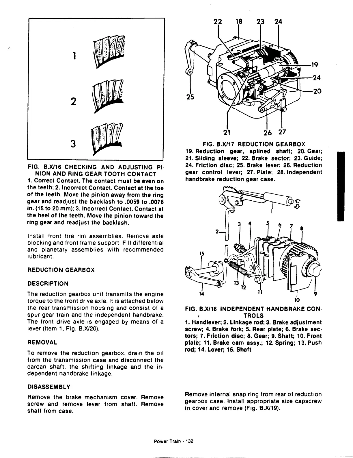
FIG. B.X/16 CHECKING AND ADJUSTING PI·
NION AND RING GEAR TOOTH CONTACT
1. Correct Contact. The
contact
must
be even on
the
teeth;
2.
Incorrect Contact. Contact at the toe
of
the teeth. Move the
pinion
away from the ring
gear and readjust the backlash to .0059 to .0078
in.
(15
to
20
mm);
3.
Incorrect Contact. Contact at
the
heel
of
the teeth. Move the
pinion
toward
the
ring gear and readjust the backlash.
Install front tire rim assemblies. Remove axle
blocking and front frame support. Fill
differential
and planetary assemblies
with
recommended
lubricant.
REDUCTION GEARBOX
DESCRIPTION
The reduction gearbox
unit
transmits
the engine
torque to the front drive axle.
It is attached below
the rear transmission housing and
consist
of
a
spur
gear train and the independent handbrake.
The front drive axle is engaged by means
of
a
lever (Item
1,
Fig. B.X/20).
REMOVAL
To remove the reduction gearbox, drain the
oil
from the transmission case and
disconnect
the
cardan shaft, the
shifting
linkage and the in·
dependent handbrake linkage.
DISASSEMBLY
Remove the brake mechanism cover. Remove
screw and remove lever from shaft. Remove
shaft from case.
FIG. B.X/17 REDUCTION GEARBOX
19. Reduction gear,
splined
shaft;
20.
Gear;
21.
Sliding sleeve;
22.
Brake sector;
23.
Guide;
24.
Friction
disc;
25. Brake lever;
26.
Reduction
gear
control
lever;
27.
Plate;
28.
Independent
handbrake
reduction
gear case.
10
FIG. B.X/18 INDEPENDENT HANDBRAKE CON·
TROLS
1. Handlever;
2.
Linkage rod;
3.
Brake
adjustment
screw;
4.
Brake fork;
5.
Rear plate; 6. Brake sec·
tors;
7.
Friction
disc;
8.
Gear;
9.
Shaft; 10. Front
plate; 11. Brake cam assy.; 12. Spring; 13. Push
rod; 14. Lever; 15. Shaft
Remove internal snap ring from rear
of
reduction
gearbox case. Install appropriate size capscrew
in cover and remove (Fig. B.X/19).
Power Train ·
132
 Loading...

