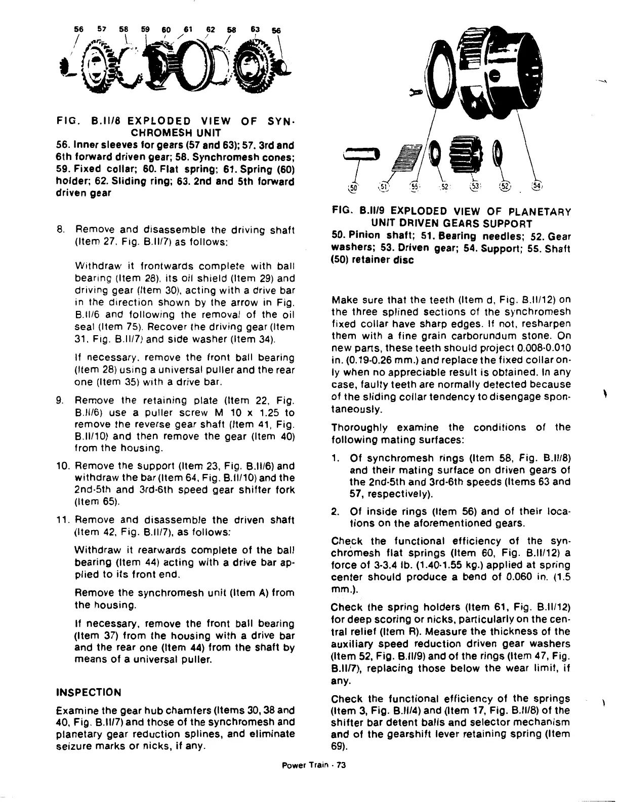
FIG.
B.ll/8
EXPLODED
VIEW
OF
SYN·
CHROMESH UNIT
56.
Inner sleeves for gears
(57
and
63);
57. 3rd and
6th
forward driven gear;
58.
Synchromesh cones;
59. Fixed collar; 60. Flat spring; 61. Spring
(60)
holder;
62.
Sliding
ring; 63. 2nd and 5th forward
driven gear
8.
Remove and disassemble the driving shaft
(Item
27.
Fig.
8.11/7)
as follows:
Withdraw it frontwards
complete
with
ball
bearing (Item
28).
its
oil shield (Item
29)
and
driving gear (Item
30),
acting
with
a drive bar
in the
direction
shown by the arrow in Fig.
8.11/6
and
following
the removal of the oil
seal (Item
75).
Recover the driving gear (Item
31.
Fig.
8.11/7)
and side washer (Item
34).
If necessary. remove the front ball bearing
(Item
28)
using a universal puller and the rear
one (Item
35)
with
a drive bar.
9.
Remove the retaining plate (Item
22,
Fig.
8.11/6)
use a puller screw M
10
x 1.25
to
remove the reverse gear shaft (Item
41,
Fig.
8.11/10)
and then remove the gear (Item
40)
from the housing.
10.
Remove the support (Item
23,
Fig.
8.11/6)
and
withdraw
the bar (Item 64, Fig.
8.11/10)
and the
2nd·5th and 3rd·6th speed gear
shifter
fork
(Item
65).
11.
Remove and disassemble the driven shaft
(Item
42,
Fig.
8.11/7),
as follows:
Withdraw
it rearwards
complete
of
the ball
bearing (Item
44)
acting
with
a drive bar ap-
plied
to
its
front end.
Remove the synchromesh
unit
(Item
A)
from
the housing.
If necessary, remove the front ball bearing
(Item
37)
from the
housing
with
a drive bar
and the rear one (Item
44)
from the shaft by
means
of
a universal puller.
INSPECTION
Examine the gear hub chamfers (Items
30,
38
and
40, Fig.
8.1117)
and those
of
the synchromesh and
planetary gear
reduction
splines, and
eliminate
seizure marks
or
nicks,
if
any.
FIG. B.ll/9 EXPLODED VIEW OF PLANETARY
UNIT DRIVEN GEARS SUPPORT
50. Pinion shaft;
51.
Bearing needles;
52.
Gear
washers;
53.
Driven gear;
54.
Support;
55.
Shaft
(50)
retainer
disc
Make sure that the teeth (Item
d,
Fig.
8.11/12)
on
the three splined
sections
of
the synchromesh
fixed
collar
have sharp edges. If not, resharpen
them
with
a fine grain carborundum stone.
On
new parts, these teeth should
project
0.008·0.010
in. (0.19-0.26 mm.) and replace the fixed
collar
on-
ly when no appreciable result is obtained. In any
case, faulty teeth are normally
detected
because
of
the
sliding
collar
tendency
to
disengage spon-
taneously.
Thoroughly
examine the
conditions
of
the
following
mating
surfaces:
1.
Of
synchromesh
rings
(Item 58, Fig.
8.1118)
and
their
mating
surface on driven gears
of
the
2nd-5th and 3rd-6th speeds (Items 63 and
57, respectively).
2.
Of
inside
rings
(Item
56)
and
of
their
loca-
tions
on the
aforementioned
gears.
Check
the
functional
efficiency
of
the syn-
chromesh
flat
springs
(Item 60, Fig.
8.11112)
a
force
of
3·3.4 lb. (1.40·1.55 kg.) applied at spring
center
should
produce a bend
of
0.060 in. (1.5
mm.).
Check
the
spring
holders
(Item 61, Fig.
8.11/12)
for
deep
scoring
or
nicks, particularly on the cen-
tral
relief
(Item
R).
Measure the
thickness
of
the
auxiliary
speed
reduction
driven gear washers
(Item 52, Fig.
8.1119)
and
of
the rings (Item 47, Fig.
8.1117),
replacing
those
below
the wear
limit,
if
any.
Check
the
functional
efficiency
of
the springs
(Item
3,
Fig.
8.1114)
and (Item 17, Fig.
8.11/8)
of
the
shifter
bar
detent
balls
and
selector
mechanism
and
of
the
gearshift
lever retaining spring (Item
69).
Power
Train·
73
'
 Loading...

