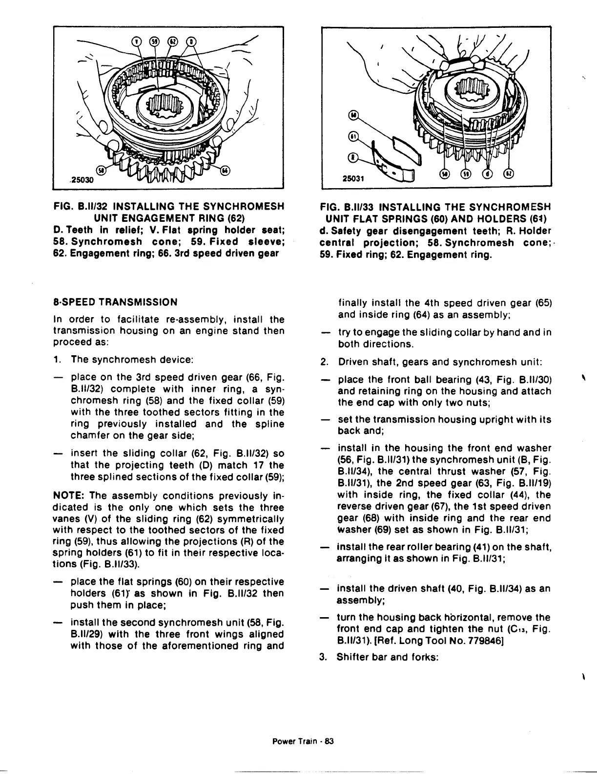
FIG.
8.11/32
INSTALLING THE SYNCHROMESH
UNIT ENGAGEMENT RING (62)
D.
Teeth In relief;
V.
Flat
spring
holder
seat;
58.
Synchromesh
cone;
59.
Fixed
sleeve;
62. Engagement ring; 66. 3rd speed driven gear
8·SPEED TRANSMISSION
In order
to
facilitate re-assembly, install the
transmission housing
on
an
engine stand then
proceed as:
1.
The synchromesh device:
place on
the
3rd speed driven gear
(66,
Fig.
8.ll/32)
complete
with
inner ring, a syn-
chromesh ring
(58)
and the fixed
collar
(59)
with
the three
toothed
sectors
fitting
in the
ring previously installed and the
spline
chamfer on the gear side;
insert the
sliding
collar
(62,
Fig.
8.11/32)
so
that the
projecting
teeth
(D)
match
17
the
three splined
sections
of
the fixed
collar
(59);
NOTE: The assembly
conditions
previously in-
dicated
is
the
only one
which
sets
the
three
vanes
(V)
of
the
sliding
ring
(62)
symmetrically
with
respect
to
the
toothed
sectors
of
the fixed
ring
(59),
thus
allowing
the
projections
(R)
of
the
spring
holders
(61)
to
fit
in
their
respective loca-
tions
(Fig.
8.11133).
place
the
flat
springs
(60)
on
their
respective
holders
(61Y
as
shown
in Fig.
8.11132
then
push
them
in place;
install
the
second synchromesh
unit
(58,
Fig.
8.11129)
with
the three
front
wings
aligned
with
those
of
the
aforementioned
ring and
FIG.
8.11133
INSTALLING THE SYNCHROMESH
UNIT FLAT SPRINGS (60) AND HOLDERS
(6~)
d. Safety gear disengagement teeth;
R.
Holder
central
projection;
58.
Synchromesh
cone;·
59.
Fixed ring; 62. Engagement ring.
finally install the 4th speed driven gear
(65)
and
inside
ring
(64)
as
an
assembly;
try
to
engage the
sliding
collar
by hand and in
both directions.
2.
Driven shaft, gears and synchromesh unit:
place the front ball bearing
(43,
Fig.
8.11130)
and retaining ring on the housing and attach
the end cap
with
only
two
nuts;
set
the
transmission
housing
upright
with
its
back and;
install in
the
housing
the front end washer
(56,
Fig.
8.11131)
the
synchromesh
unit
(8, Fig.
8.11134),
the
central
thrust
washer
(57,
Fig.
8.11131),
the 2nd speed gear
(63,
Fig.
8.11119)
with
inside
ring,
the
fixed
collar
(44),
the
reverse driven gear
(67),
the 1st speed driven
gear
(68)
with
inside
ring and
the
rear end
washer
(69)
set as shown in Fig.
8.11131;
install
the
rear
roller
bearing
(41)
on
the
shaft,
arranging
it
as
shown
in Fig.
8.11131;
install
the
driven shaft
(40,
Fig.
8.11/34)
as an
assembly;
turn the
housing
back horizontal, remove the
front end cap and
tighten
the
nut
(Cu,
Fig.
8.11131).
[Ref. Long Tool No. 779846)
3.
Shifter bar and forks:
Power
Train·
83
'
 Loading...

