C.ll FITS &
TOLERANCES-
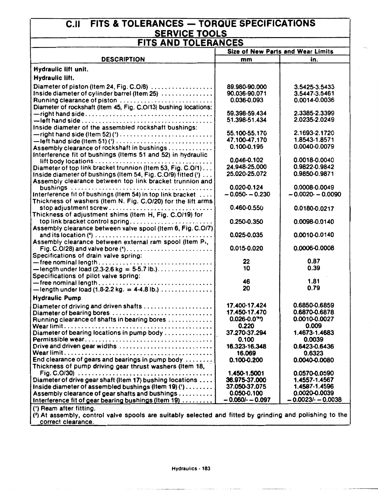
TORQUE SPECIFICATIONS
SERVICE TOOLS
FITS AND TOLERANCES
Hydraulic
lift
unit.
Hydraulic
lift.
DESCRIPTION
Diameter
of
piston
(Item 24, Fig. C.0/8)
.................
.
Inside diameter
of
cylinder barrel (Item
25)
..............
.
Running clearance
of
piston
..........................
.
Diameter
of
rockshaft (Item
45,
Fig. C.0/13) bushing locations:
-right
hand side
........
,
...........................
.
-left
hand side
.....................................
.
Inside diameter
of
the assembled rockshaft bushings:
-right
hand siqe (Item 52)(')
..........................
.
-left
hand side (Item 51)(')
...........................
.
Assembly clearance
of
rockshaft in bushings
............
.
Interference
fit
of
bushings (Items
51
and
52)
in hydraulic
lift
body locations
.................................
.
Diameter
of
top link bracket trunnion (Item
53,
Fig. C.0/1)
..
.
Inside diameter
of
bushings (Item
54,
Fig. C.0/9)
fitted(')
..
.
Assembly clearance between top
link
bracket trunnion and
bushings
........................................
.
Interference
fit
of
bushings (Item
54)
in top
link
bracket
...
.
Thickness
of
washers (Item
N.
Fig. C.0/20)
for
the
lift
arms
stop adjustment screw
.............................
.
Thickness
of
adjustment
shims
(Item
H,
Fig. C.0/19) for
top
link bracket control spring
.......................
.
Assembly clearance between valve spool (Item
6,
Fig. C.0/7)
and
its
location
(•)
.................................
.
Assembly clearance between external ram spool (Item
P,,
Fig. C.0/28) and valve bore
(•)
........................
.
Specifications
of
drain valve spring:
-free
nominal length
................................
.
-length
under load (2.3-2.6 kg = 5-5.7 lb.)
...............
.
Specifications
of
pilot
valve spring:
-free
nominal length
................................
.
-length
under load (1.8-2.2 kg. = 4-4.81b.)
..............
.
Hydraulic Pump
Diameter
of
driving and driven shafts
...................
.
Diameter
of
bearing bores
............................
.
Running clearance
of
shafts in bearing bores
............
.
Wear
limit
..........................................
.
Diameter
of
bearing locations in
pump
body
.............
.
Permissible wear. . . . . . . . . . . . . . . . . . . . . . . . . . . . . . . . . . . . . ·
Drive and driven gear
widths
..........................
.
Wear
limit
..........................................
.
End clearance
of
gears and bearings in pump body
.......•
Thickness
of
pump driving gear
thrust
washers (Item 18, ·
Fig. C.0/30)
.................•...............•.....
Diameter
of
drive gear shaft (Item 17) bushing
locations
...
.
Inside diameter
of
assembled bushings (Item
19)
(')
..
_
....
.
Assembly clearance
of
gear shafts and bushings
.........
.
Interference
fit
of
aear bearina
bushinas
ntem
19)
........
.
(') Ream after
fitting.
Size
of
New Parts and Wear
Limits
mm
89.980-90.000
90.036-90.071
0.036-0.093
59.398-59.434
~1.398-51.434
55.100-55.170
47.100-47.170
0.100-0.195
0.046-0.102
24.948-25.000
25.020-25.072
0.020-0.124
- 0.050- - 0.230
0.460-0.550
0.250-0.350
0.025-0.035
0.015·0.020
22
10
46
20
17.400·17.424
17.450·17.470
0.026-0.0'7')
0.220
37.270-37.294
0.100
16.323·16.348
16.069
0.100-0.200
1.450-1.5001
36.975-37.000
37.050-37.075
0.050-0.100
-
0.0601·
- 0.097
in.
3.5425-3.5433
3.544
7-3.5461
0.0014-0.0036
2.3385-2.3399
2.0235-2.0249
2.1693-2.1720
1.8543-1
.85
71
0.0040-0.0079
0.0018-0.0040
0.9822-0.9842
0.9850-0.9871
0.0008·0.0049
- 0.0020- - 0.0090
0.0180-0.0217
0.0098-0.0140
0.0010-0.0140
0.0006-0.0008
0.87
0.39
1.81
0.79
0.6850·0.6859
0.6870-0.6878
0.0010-0.0027
0.009
1.4673·1.4683
0.0039
0.6423-0.6436
0.6323
0.0040-0.0080
0.0570-0.0590
1.4557·1.4567
1.4587 ·1.4596
0.0020-0.0039
- 0.0023/· - 0.0038
(2)
At assembly,
control
valve
spools
are
suitably
selected and
fitted
by grinding and polishing
to
the
correct clearance.
Hydraulics • 183

 Loading...
