A.lll CRANK GEAR ASSEMBLY
GENERAL
The
normalized
steel
crankshaft
has
its
counterweights
integral
with
the crank arms,
revolves in thin-shell type bearings
with
anti-
friction
metal lining and is supported by 4 main
bearings.
Pistons
are made
of
an
aluminum
alloy
possessing high resistance
to
both
mechanical
and heat stresses. Its
combustion
chambers are
internal and the truncated cone shaped
skirt
has
an
elliptical
base
with
the
major
diameter
at
90
•
from
the pin axis.
Each
piston
is fitted
with
three rings arranged,
from
top down, as follows:
1.
First compression ring,
with
convex, chrome
plated outside surface.
2.
Second ring,
compression
ring.
3.
Third ring. oil scraper, backbone type,
chrome plated and
with
inside coil spring.
The forged steel channel shaped
connecting
rods are drilled along the length
for
cylinder
liner
lubrication
and are provided
with
thin
shell
bearings
with
anti-friction
metal
lining
on big
end and sleeve bearings on small end.
CRANKSHAFT
The crankshaft can be removed from the
engine
only
after removing the latter from the tractor. In-
stall
the engine on the shop turnover stand, then
remove the
following
parts:
1.
Cylinder head (if
pistons
also are
to
be
removed, see page
25).
2.
Oil
sump
(as
outlined
on page
14).
3.
Oil pump (Item
2,
Fig. A.lll/1).
4.
Hydraulic
Circuit
Pump (Item
P).
5.
Injection
Pump Gear Compartment Lid (Item
7),
located on the
timing
gear cover.
6. V-belt (Item
6),
after
slackening
the
alternator
attaching
bolt
(Item
C2,
Fig. A.VI/6).
7.
Drive
pulley
(Item
5)
and
its
hub
with
a plate
puller
with
slots
at 120 • (Fig. A.lll/2).
8. Fan and Driven Pulley.
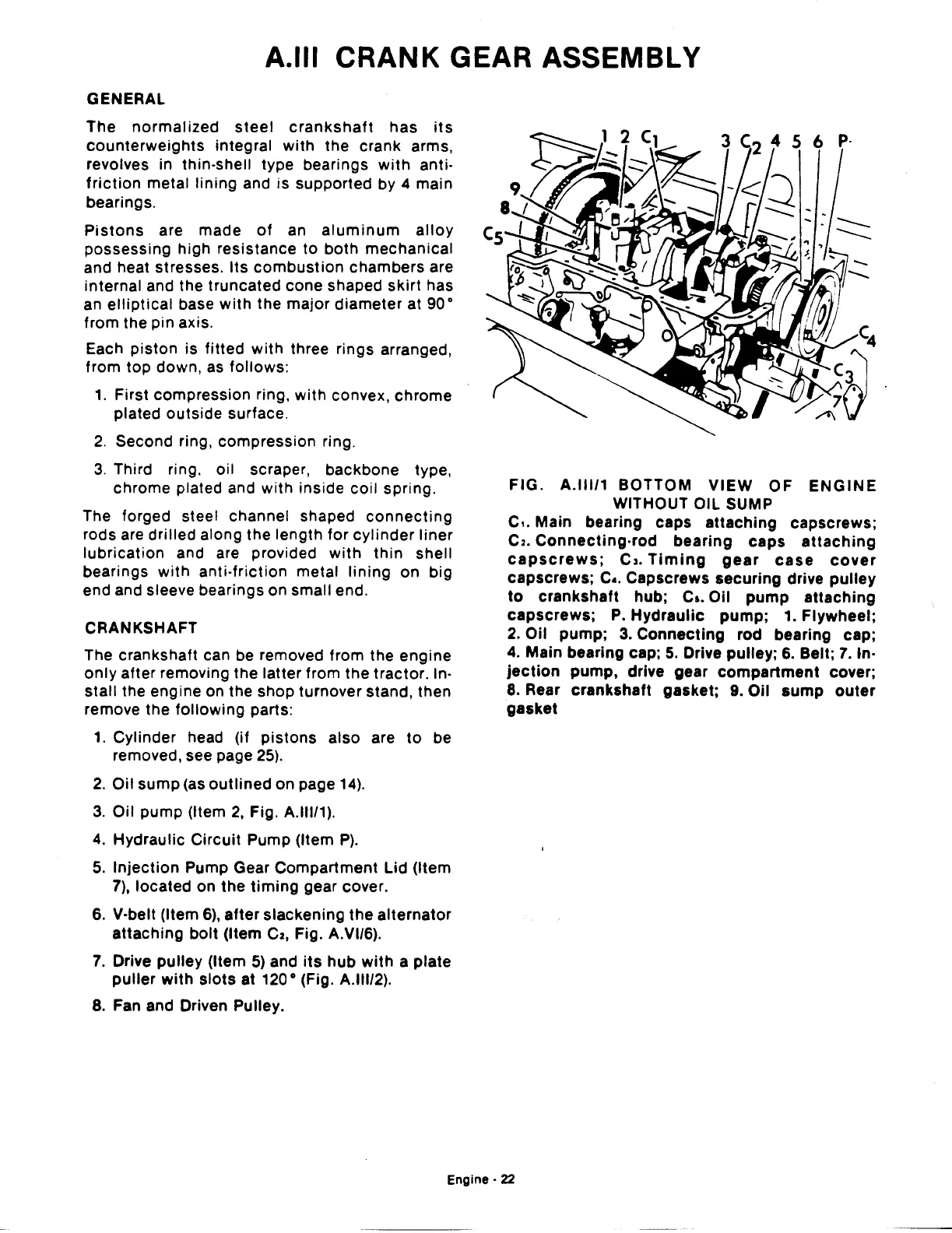
FIG.
A.lll/1
BOTTOM
VIEW
OF
ENGINE
WITHOUT OIL SUMP
c,.
Main bearing caps
attaching
capscrews;
C2.
Connecting-rod
bearing
caps
attaching
capscrews;
CJ.
Timing
gear
case
cover
capscrews; c
•.
Capscrews securing drive
pulley
to
crankshaft hub;
Ca.
Oil
pump
attaching
capscrews;
P.
Hydraulic
pump;
1.
Flywheel;
2.
Oil
pump;
3.
Connecting
rod bearing cap;
4. Main bearing cap;
5.
Drive pulley;
6.
Belt;
7.
In-
jection
pump,
drive gear
compartment
cover;
8. Rear
crankshaft
gasket; 9. Oil
sump
outer
gasket
Engine·
22
 Loading...

