AXLE REMOVAL
If the
following
procedures have
not
been per-
formed, they
must
be
done
before the axle can
be removed.
1.
Drain
lubricant
from planetary drives and
dif·
ferential.
Position
stand on
either
side
of
the
differential
to
relieve axle
weight
and prevent
axle from
oscillating.
Remove tire and rim
assemblies.
2.
Pull tie rod end at
spindle
support. Remove
spindle retaining cap
screws
at the
spindle
support, and pull planetary
assembly
com-
plete.
To
remove the axle, loosen
lock
nut
and remove
axle
set screw located on the rear
of
the axle
housing.
Place a
block
beneath
inner
yoke
of
the universal
joint.
and pry the axle outward
until
the
0-ring
seal is free of the
housing.
Remove the axle
shaft.
AXLE DISASSEMBLY
To
disassemble
the axle, remove the
0-ring
seal,
external snap ring and internal bearing retaining
snap ring. Pull roller bearing
from
bearing
re-
tainer
and remove inner retaining snap ring.
Press seal from hOusing
(F1g.
B.X/10).
AXLE INSPECTION
Clean all parts and
check
for
defects.
Check the
axle
universal for worn or damaged parts and
replace as required.
AXLE REASSEMBLE
Place the
inner
bearing retaining snap ring in the
retainer and insert ball bearing. Locate the ball
bearing
against
inner retaining snap ring.
Install
the
outer retaining snap ring. Invert bearing re-
tainer
and
insert
seal.
Locate
the seal
against
in-
ner
bearing retaining snap ring.
Slide
the
0-ring
over the seal end
of
the bearing
retainer. Run
the
bearing retainer and bearing
assembly
over the
length
of
the shaft, and
locate
against
the
shoulder
on
the
axle.
Install
internal
snap
ring
against
the bearing race.
DIFFERENTIAL REMOVAL
Before
the
differential
can be removed
for
in-
spection
or
overhaul,
the
front drive
axle
must
be
removed
from
the tractor, and
both
of
the
planetary
drives
and drive axle
shafts
must
be
removed.
Remove
differential
support
retaining
screws
(Item
Cl, Fig. B.X/6) and
lift
differential
support
from
axle
housing.
8~
6
7
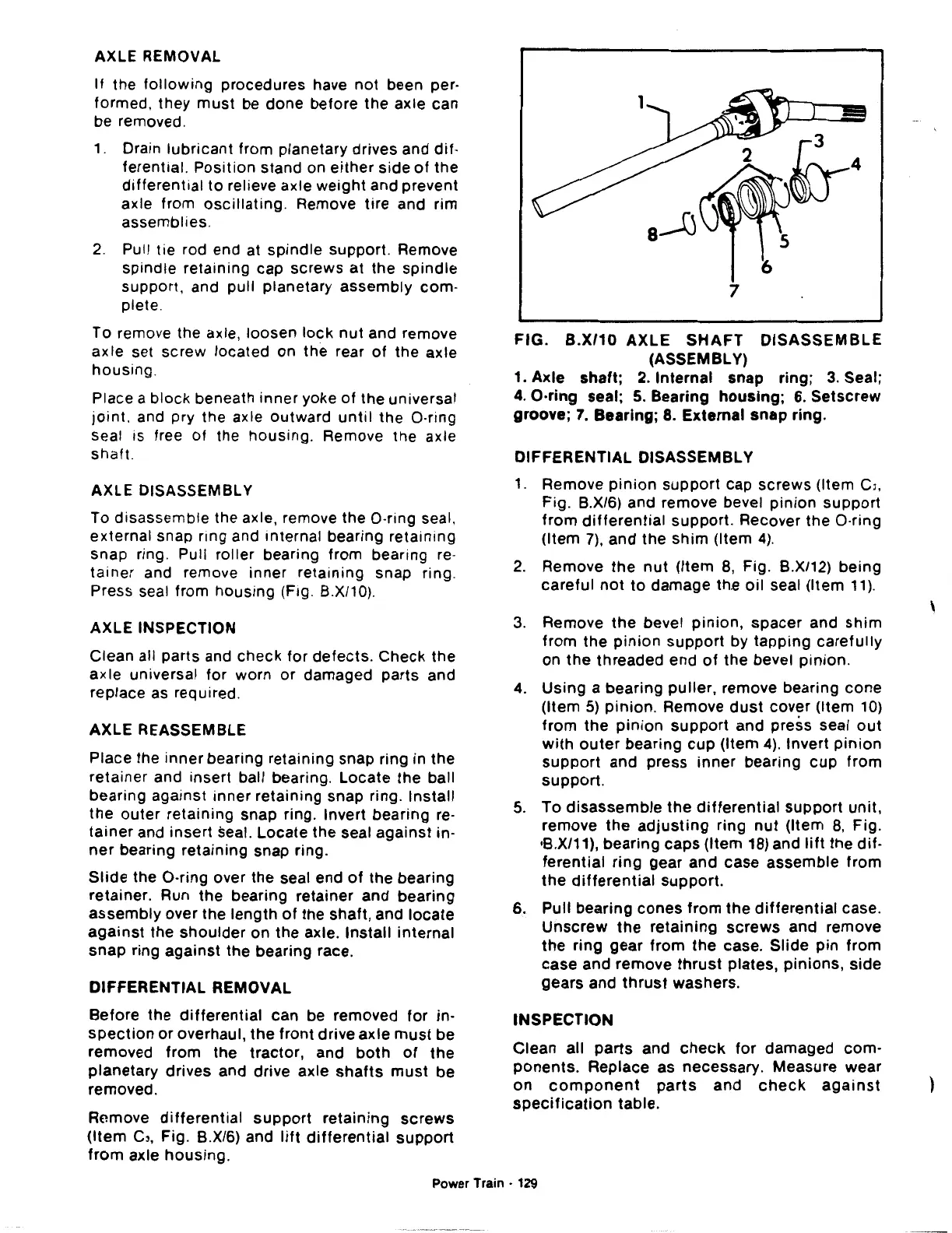
FIG.
B.X/10
AXLE
SHAFT
DISASSEMBLE
(ASSEMBLY)
1.
Axle
shaft;
2.
Internal
snap ring;
3.
Seal;
4.
O·ring seal;
5.
Bearing
housing;
6.
Setscrew
groove;
7.
Bearing;
8. External
snap
ring.
DIFFERENTIAL DISASSEMBLY
1.
Remove
pinion
support
cap
screws
(Item
CJ,
Fig. B.X/6) and remove bevel
pinion
support
from
differential
support. Recover the
0-ring
(Item
7),
and the
shim
(Item
4).
2.
Remove
the
nut
(Item
8,
Fig. B.X/12)
being
careful
not
to
damage
th.e
oil
seal (Item
11).
3.
Remove
the
bevel
pinion,
spacer
and
shim
from
the
pinion
support
by
tapping
carefully
on
the
threaded end
of
the bevel
pinion.
4.
Using
a bearing
puller,
remove bearing
cone
(Item
5)
pinion.
Remove
dust
cover (Item
10)
from
the
pinion
support
and
press
seal
out
with
outer
bearing
cup
(Item
4).
Invert
pinion
support
and
press
inner
bearing
cup
from
support.
5.
To
disassemble
the
differential
support
unit,
remove
the
adjusting
ring
nut
(Item
8,
Fig.
•B.X/11), bearing
caps
(Item
18)
and
lift
the
dif-
ferential
ring
gear
and
case
assemble
from
the
differential
support.
6.
Pull bearing
cones
from
the
differential
case.
Unscrew
the
retaining
screws
and remove
the
ring
gear
from
the
case.
Slide
pin
from
case
and remove
thrust
plates,
pinions,
side
gears
and
thrust
washers.
INSPECTION
Clean all
parts
and
check
for
damaged com-
ponents.
Replace as necessary. Measure wear
on
component
parts
and
check
against
specification
table.
Power Train - 129
'
 Loading...

