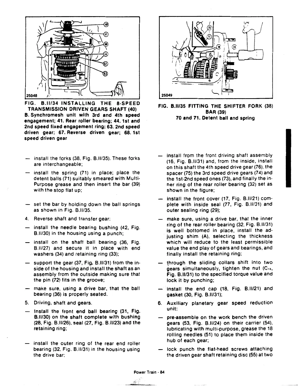
FIG.
B.ll/34
INSTALLING
THE
8-SPEED
TRANSMISSION DRIVEN GEARS SHAFT (40)
B.
Synchromesh
unit
with
3rd and 4th speed
engagement;
41.
Rear roller bearing; 44. 1st and
2nd speed fixed engagement ring; 63. 2nd speed
driven gear; 67. Reverse driven gear; 68. 1st
speed driven gear
install the forks
(38,
Fig. B.ll/35). These forks
are interchangeable;
install the spring
(71)
in place; place the
detent
balls
(71)
suitably
smeared
with
Multi·
Purpose grease and then insert the bar
(39)
with
the
stop
flat up;
set the bar by
holding
down
the ball springs
as shown in Fig. B.ll/35.
4.
Reverse shaft and
transfer
gear:
install the needle bearing
bushing
(42,
Fig.
B.ll/30) in the
housing
using a punch;
install on the
shaft
ball bearing (36, Fig.
B.ll/27) and secure
it
in place
with
end
washers
(34)
and retaining ring
(33);
support the gear
(37,
Fig. B.ll/31)
from
the in-
side
of
the
housing
and
install
the
shaft
as an
assembly from the
outside
making sure that
the pin
(72)
fits
in the groove;
make sure,
using
a drive bar, that the ball
bearing
(36)
is
properly seated.
5.
Driving, shaft and gears.
Install the
front
end ball bearing (31, Fig.
8.11130)
on
the
shaft
complete
with
bushing
(28,
Fig.
8.11126),
seal (27, Fig. B.ll/23) and the
retaining ring;
install the
outer
ring
of
the rear end roller
bearing
(32.
Fig. B.ll/31) in the
housing
using
the drive bar:
FIG. B.ll/35 FITTING THE SHIFTER FORK
(38)
BAR (39)
70
and 71. Detent ball and spring
install
from the front driving shaft assembly
(16,
Fig. B.ll/31) and, from the inside, install
on
this
shaft the 4th speed drive gear
(76),
the
spacer
(75)
the 3rd speed drive gears
(74)
and
the 1st-2nd speed ones
(73),
and finally the in-
ner ring
of
the rear roller bearing
(32)
set as
shown
in the figure;
install
the
front
cover
(17,
Fig. B.ll/21) com-
plete
with
inside seal
(77,
Fig. B.ll/31) and
outer
sealing ring
(29);
make sure, using a drive bar, that the inner
ring
of
the rear roller bearing
(32,
Fig. B.ll/31)
is
well
bottomed
in place, install the ad-
justing
shim
(A),
selecting
the
thickness
which
will
reduce
to
the least permissible
value the end play
of
gears and bearings, and
finally
install the retaining ring;
t,hrough the
sliding
collars
shift
into
two
gears simultaneously,
tighten
the
nut
(C13,
Fig. B.ll/31)
to
the
specified
torque value and
lock
it
by punching;
install
the end cap (18, Fig. B.ll/21) and
gasket
(30,
Fig. B.ll/31);
6.
Auxiliary
planetary gear speed reduction
unit:
pre-assemble
on
the
work bench
the
driven
gears (53, Fig.
8.11/24)
on
their
carrier
(54),
lubricating
with
multi-purpose, grease the 18
rolling
needles
(51)
to
place them inside the
hub
of
each gear;
lock
punch
the
flat-head screws
attaching
the driven gear shaft retaining
disc
(55)
at
two
Power Train •
84
 Loading...

