15217
FIG. A.VI/4
THERMOSTAT
REMOVAL
(IN·
STALLATION)
14. Gasket; 15. Cover
THERMOSTAT
The thermostat is located inside the cylinder
head water outlet pipe terminal.
To remove it, loosen the band clamps, discon·
nect the hose and remove the cover (Item
15,
Fig.
A.VI/4).
Check by immersing it in a container
of
water
along
with
,a temperature gauge. Thermostat
begins
to
open at 181.4 •
to
203 •F.
(83
•
to
95
•c.)
It is fully open at 203 •F.
(95
•c.).
A WARNING:
DO
NOT OPERATE TRACTOR WITHOUT THER·
MOSTAT. OVERHEATING COULD RESULT AND
CAUSE ENGINE DAMAGE.
REPLACING THE FAN AND ALTERNATOR
DRIVE BELT
No
tractor part needs
to
be removed first. Pro·
ceed as follows:
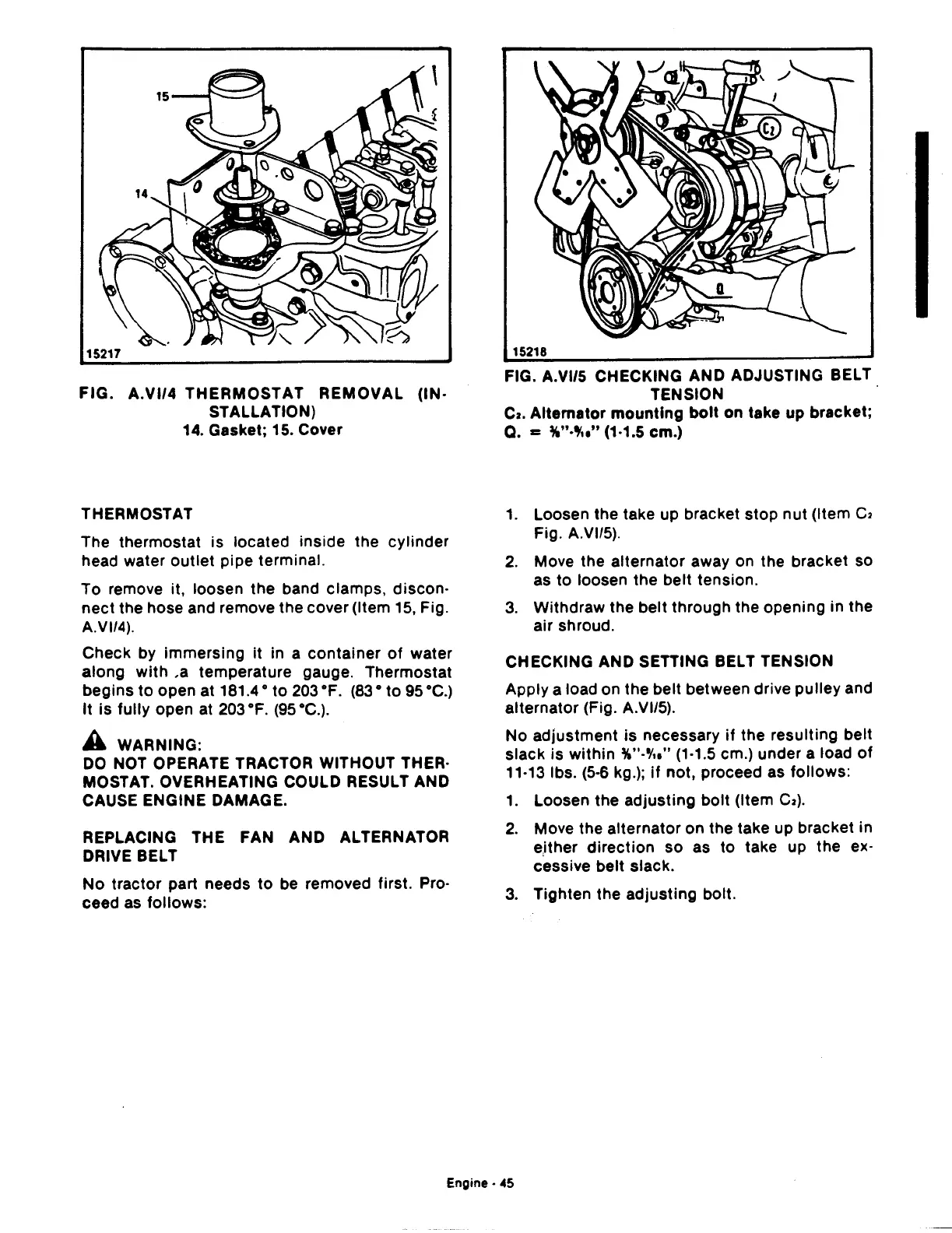
15218
FIG. A.VI/5 CHECKING AND ADJUSTING BELT
TENSION
Cz.
Alternator
mounting
bolt
on take up bracket;
Q.
=
%"·'""
(1·1.5 em.)
1.
Loosen the take up bracket stop nut (Item
C2
Fig. A.VI/5).
2.
Move the alternator away on the bracket so
as to loosen the belt tension.
3.
Withdraw the belt through the opening in the
air shroud.
CHECKING AND SETTING BELT TENSION
Apply a load on the belt between drive pulley and
alternator (Fig. A.VI/5).
No adjustment
is
necessary
if
the resulting belt
slack is within
%"-'/,," (1·1.5 em.) under a load
of
11·13 lbs.
(5·6
kg.);
if
not, proceed as follows:
1.
Loosen the adjusting bolt (Item
C2).
2.
Move the alternator on the take up bracket in
e,ither
direction
so as
to
take up the ex·
cessive belt slack.
3.
Tighten the adjusting bolt.
Engine·
45
 Loading...

