ASSEMBLY
At
assembly, take
notice
of
the
following
items:
1.
When
installing
the
pinion
shaft and
the
axle
shaft
be careful
not
to
damage
the
seal
(Items
12
and 13, Fig. B.VI/7).
2.
Fit the
outer
roller
bearing
inner
ring (Item
7,
Fig. B.VI/5)
to
the
pinion
shaft.
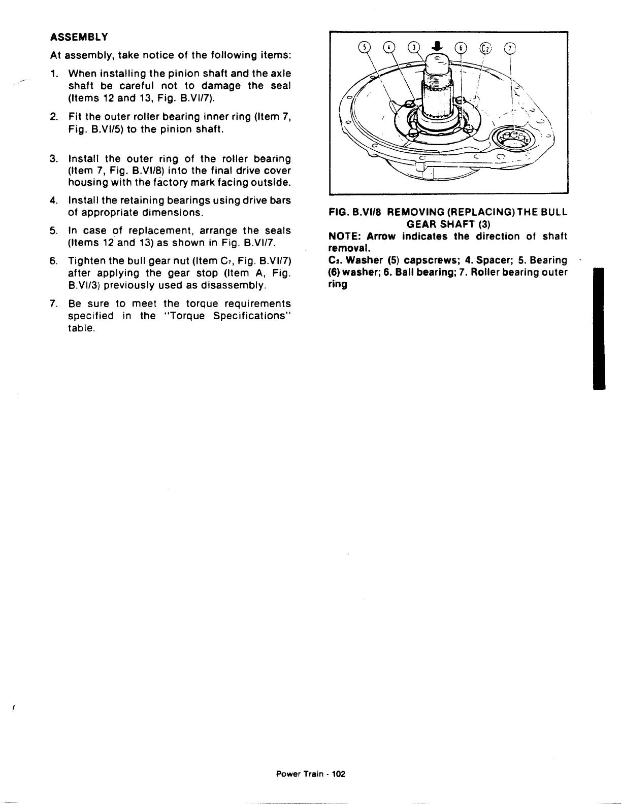
3.
Install the
outer
ring
of
the roller bearing
(Item
7,
Fig. B.VI/8)
into
the final drive cover
housing
with
the
factory
mark facing outside.
4.
Install the retaining bearings
using
drive bars
of
appropriate
dimensions.
5. In case
of
replacement, arrange the seals
(Items
12
and
13)
as
shown
in Fig. B.VI/7.
6.
Tighten the bull gear
nut
(Item
C1,
Fig. B.VI/7)
after applying the gear
stop
(Item
A,
Fig.
B.VI/3) previously used as disassembly.
7.
Be
sure
to
meet
the
torque requirements
specified
in the
"Torque
Specifications"
table.
FIG. B.VI/8 REMOVING (REPLACING) THE BULL
GEAR SHAFT
(3)
NOTE: Arrow
indicates
the
direction
of
shaft
removal.
C2.
Washer
(5)
capscrews; 4. Spacer; 5. Bearing
(6) washer; 6. Ball bearing;
7.
Roller bearing
outer
ring
Power Train · 102
 Loading...

