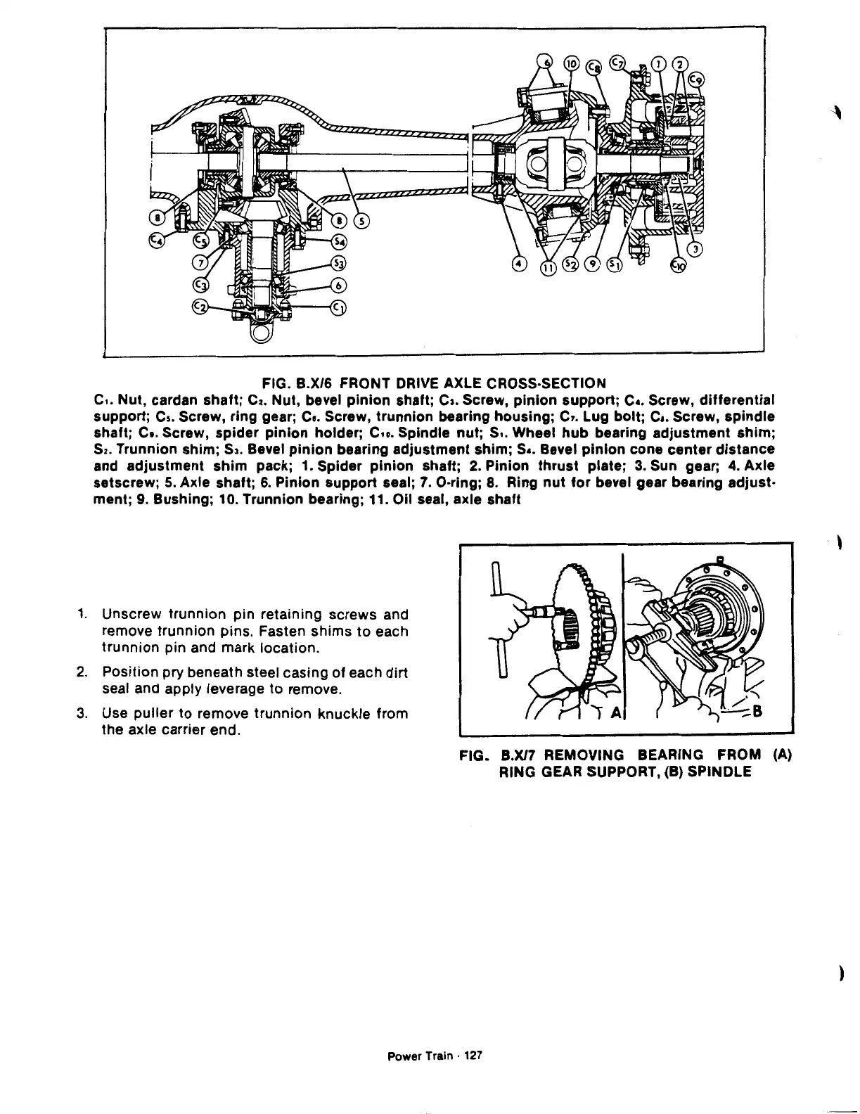
FIG. B.X/6 FRONT
DRIVE
AXLE CROSS-SECTION
c
..
Nut, cardan shaft;
C2.
Nut, bevel pinion shaft;
c,.
Screw, pinion support; c
•.
Screw, differential
support;
Cs.
Screw, ring gear;
Ca.
Screw, trunnion bearing housing; c,. Lug bolt;
Ca.
Screw, spindle
shaft;
c
•.
Screw, spider pinion holder;
C.o.
Spindle nut; s
•.
Wheel
hub
bearing adjustment shim;
S2.
Trunnion shim;
53.
Bevel pinion bearing adjustment shim; s
•.
Bevel pinion cone center distance
and adjustment shim pack; 1. Spider pinion shaft;
2. Pinion thrust plate;
3.
Sun gear;
4.
Axle
setscrew;
5.
Axle shaft;
6.
Pinion support seal;
7.
O·ring;
8.
Ring
nut
for
bevel gear bearing adjust·
ment;
9.
Bushing; 10. Trunnion bearing; 11. Oil seal, axle shaft
1.
Unscrew trunnion pin retaining screws and
remove trunnion pins. Fasten shims
to
each
trunnion pin and mark location.
2.
Position pry beneath steel casing of each dirt
seal and apply leverage
to
remove.
3.
Use puller
to
remove trunnion knuckle from
the axle carrier end.
FIG. B.X/7 REMOVING BEARING FROM (A)
RING GEAR SUPPORT,
(B)
SPINDLE
Power Train ·
127
)
 Loading...

