into
threaded bore
of
cylinder
rod
(9)
snug
tight
and set clamp
(29).
Bolt
on
cylinder
head
(20),
and
attach
miscellaneous
brackets and
tubing
connections.
A
CAUTION-Lock
nut
(46)
is
still
loose.
After
nut
is
installed
on
tractor
and
alignment
assured
for
free
rocking
movement
of
ball
joints,
do
not
forget
to
tighten
lock
nut
(46)
and set tab
of
safety plate.
Inspect
all
exterior
tubing
connections
and
fastenings:
lock
tabs and
cotter
pins.
Start
tractor
engine
and
allow
cylinder
to
fill
with
oil. Rock steering wheel several times. Cylinder
nearly always purges
itself
of
air, but in event
spongy operation
indicates
airlock, bleed
with
intake line
disconnected;
work steering
cylinder
against
limits
several times. Turn wheel
until
cylinder
is
fully
extended, reconnect inlet hose
finger-tight. Start engine and
allow
oil and air to
trickle
out around
connector
for
2·3 minutes.
Tighten
connector
with
pressure
still
present in
lines.
OPERATION (MICO)
The operation
of
the MICO power steering
cylinder
is
similar
to
the UTB cylinder.
CYLINDER DISASSEMBLY
The MICO power steering
cylinder
can be
disassembled
only
into
two
groups, the
cylinder
and the valve.
Disconnect
hoses from the cylinder. Remove the
cylinder
from the tractor. Recover
grommet
and
washer from shaft end
of
cylinder. Remove
bolts
from
control
valve end. Separate
cylinder
from
control
valve.
To replace
wiper
ring, remove snap ring from
groove
inside
cylinder
barrel. Replace
wiper
ring.
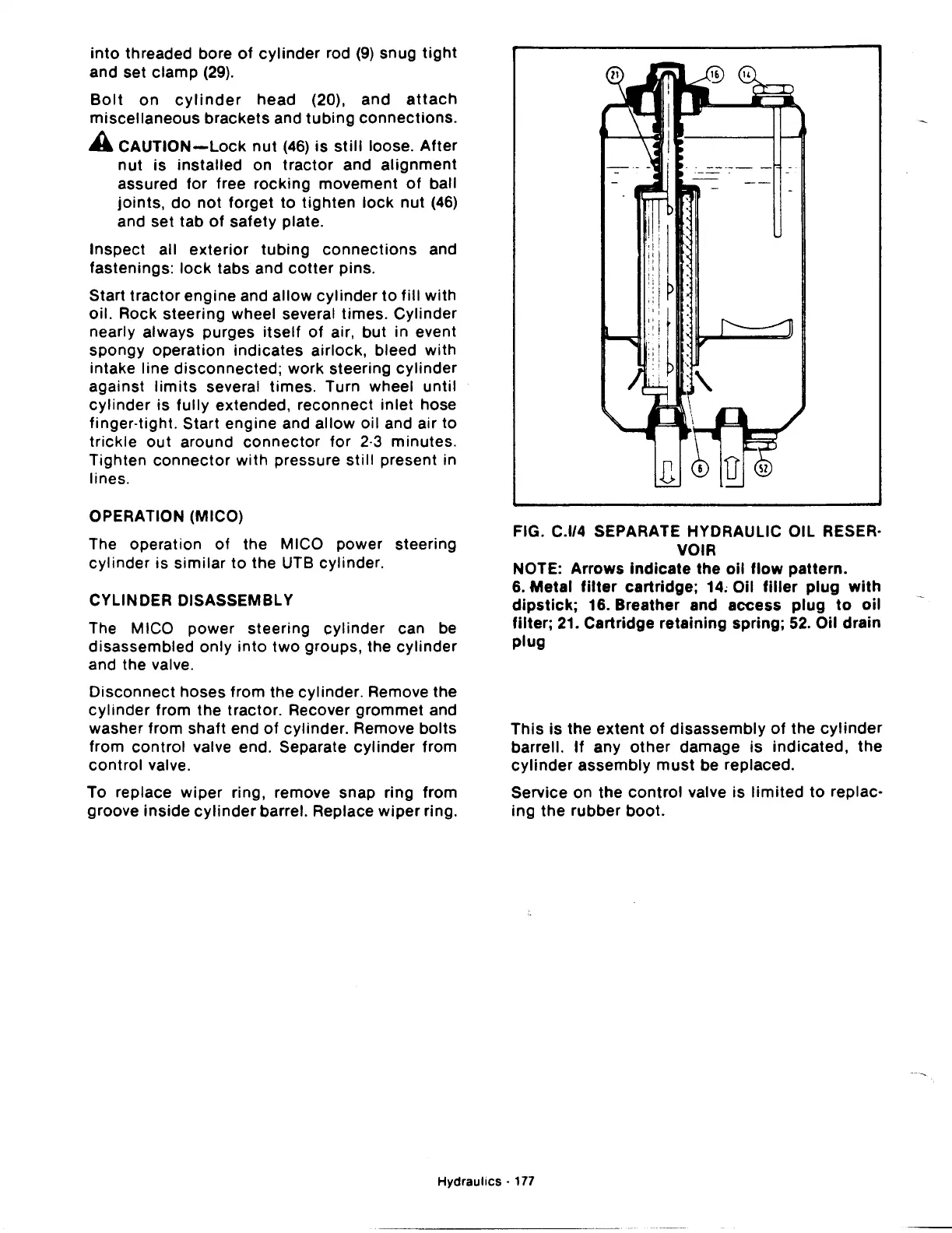
FIG. C.l/4 SEPARATE HYDRAULIC OIL RESER·
VOIR
NOTE: Arrows
indicate
the
oil
flow
pattern.
6.
Metal
filter
cartridge;
14~
Oil
filler
plug
with
dipstick;
16. Breather and access
plug
to
oil
filter;
21. Cartridge
retaining
spring;
52.
Oil drain
plug
This
is
the
extent
of
disassembly
of
the
cylinder
barrel!.
If
any
other
damage
is
indicated,
the
cylinder
assembly
must
be replaced.
Service on the
control
valve
is
limited
to
replac-
ing
the
rubber
boot.
Hydraulics·
177
 Loading...

