2
1--o
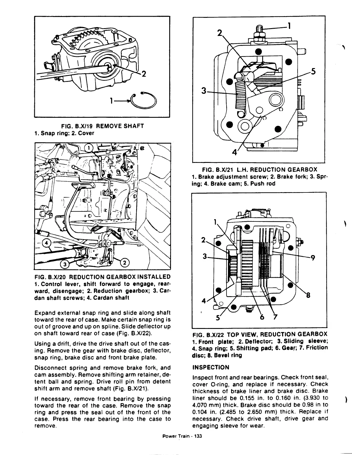
FIG. B.X/19 REMOVE SHAFT
1. Snap ring;
2.
Cover
FIG. B.X/20 REDUCTION GEARBOX INSTALLED
1.
Control lever,
shift
forward
to
engage, rear·
ward, disengage;
2.
Reduction gearbox;
3.
Car·
dan
shaft
screws;
4.
Cardan shaft
Expand external snap ring and slide along shaft
toward the rear
of
case. Make certain snap ring is
out
of
groove and up on spline. Slide
deflector
up
on shaft toward rear
of
case (Fig. B.X/22).
Using a
drift,
drive the drive shaft out
of
the cas·
ing. Remove
the
gear
with
brake disc, deflector,
snap ring, brake
disc
and front brake plate.
Disconnect
spring and remove brake fork, and
cam assembly. Remove
shifting
arm retainer, de-
tent
ball and spring. Drive roll pin from detent
shift
arm and remove shaft (Fig. B.X/21
).
If
necessary, remove
front
bearing by pressing
toward the rear
of
the case. Remove the snap
ring and press the seal
out
of
the
front
of
the
case. Press
the
rear bearing
into
the case to
remove.
5
FIG.
B.X/21
L.H. REDUCTION GEARBOX
1.
Brake adjustment screw;
2.
Brake fork;
3.
Spr·
ing;
4.
Brake cam;
5.
Push rod
FIG. B.X/22 TOP VIEW, REDUCTION GEARBOX
1~
Front plate; 2. Deflector; 3.
Sliding
sleeve;
4.
Snap ring;
5.
Shifting
pad; 6. Gear;
7.
Friction
disc;
8. Bevel ring
INSPECTION
Inspect front and rear bearings. Check front seal,
cover 0-ring, and replace
if
necessary. Check
thickness
of
brake liner and brake disc. Brake
liner should be 0.155 in.
to
0.160 in. (3.930 to
4.070 mm)
thick.
Brake
disc
should be 0.98 in to
0.104 in. (2.485 to 2.650 mm)
thick.
Replace
if
necessary. Check drive shaft, drive gear and
engaging sleeve for wear.
Power Train ·
133
'
'
)

 Loading...
