2.
Introduce
into
the right casing a planetary pi·
nion
(36)
only
after
fitting
an
adjusting
screw
(35)
on
its
cylindrical side.
3.
Fit
on the planetary
pinion
the shaft, already
prepared,
fixing
the pin
of
the shaft in the
right
casing hole.
4.
Over the
spider
pinions
put the second
planetary
pinion
provided
with
adjusting
screw.
5.
Over them apply the
left
casing and tighten
the self-locking screws
(Items.,
Fig. B.IX/11)
at a torque value
of
18·25 ft. lbs. (24·34 N·M).
6.
Check,
rotating
by hand the clearance bet·
ween planetary
pinions
and
spider
pinions
flanks
which
must
be
within
.006·.008 in.
(0.15·0.20 mm.) and can be set by means of
the
adjusting
rings.
They
must
rotate freely.
After
performing
this
operation, remove the
left
casing so that the planetary pinion and the thrust
ring
to
remain in the right casing assembly.
7.
Press on the bevel gearing the
left
casing
and
tighten
the self-locking screws at a tor·
que of 51·56 lbs. (69·76 N-m).
8.
Insert from the inside the
two
buttons
M12
and fully
tighten
them
with
the respective
nuts
and secure by bending circlips.
9.
Assemble the
two
casings and
tighten
the 8
screws previously removed, at a torque
of
18·25 ft. lbs. (24·34 N·m).
10.
Simultaneously
press the inner races
of
the
tapered roller bearings (Item
32,
Fig. B.IX/12)
on the
two
casings.
The
establishment
for
the
shims
for the bevel pi·
nion is made by means
of
a device as indicated
on Fig. B.IX/13.
1.
Press
inside
the
differential
drive
pinion
sup·
port the tapered roller bearings
inner
races
(49 and
51).
2.
Insert in the
adjusting
device the inner races
of
the tapered roller bearings
(49
and
51)
and
the
drive
pinion
support
(43);
finally
tighten
the
device
nut.
Then rotate the drive
pinion
support
about
10
turns
in
order
to
seat
the rollers on the races; measure
dimension
L, (Fig. B.IX/13).
Remove the parts from the device,
withdraw
the
drive pinion
support
and
fit
in place the bearing
inner races and the bushing. Measure
dimension
L2.
The
shims
thickness
must
be as
follows:
s,
=
(l··l2)
+ .002 in. (0.05 mm.).
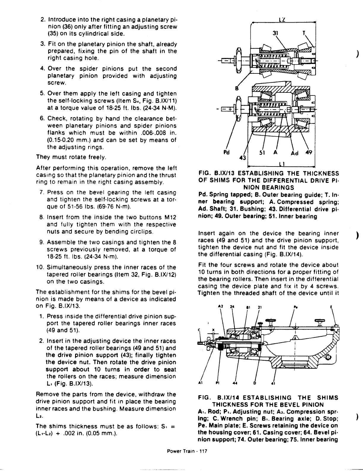
FIG. B.IX/13 ESTABLISHING THE THICKNESS
OF SHIMS FOR THE DIFFERENTIAL DRIVE PI·
NION BEARINGS
Pd. Spring tapped;
B.
Outer bearing guide;
T.
In·
ner
bearing
support;
A. Compressed spring;
Ad. Shaft;
31.
Bushing; 43. Differential drive pi·
nion;
49. Outer bearing;
51.
Inner bearing
Insert again on the device the bearing inner
races (49 and 51) and the drive
pinion
support,
tighten
the device
nut
and
fit
the device inside
the
differential
casing (Fig. B.IX/14).
Fit
the four
screws
and rotate the device about
10
turns
in
both
directions
for a proper
fitting
of
the bearing rollers. Then insert in the
differential
casing the device plate and fix it by 4 screws.
Tighten
the threaded
shaft
of
the
device
until
it
FIG. B.IX/14
ESTABLISHING
THE
SHIMS
THICKNESS FOR THE BEVEL PINION
A
•.
Rod; P
•.
Adjusting
nut;
A2.
Compression spr·
lng;
C.
Wrench
pin;
B
•.
Bearing axle;
D.
Stop;
Pe. Main plate;
E.
Screws retaining the device on
the
housing
cover;
61.
Casing cover; 64.
Be•wel
pi·
nion
support;
74.
Outer bearing; 75. Inner bearing
Power
Train·
117
)
)
)
 Loading...

