A.IV. FUEL SYSTEM
AIR SUPPLY
The air aspirated
into
the cylinders is
first
filtered through an oil-bath cleaner
with
a self·
cleaning, pre-cleaner (Item
9,
Fig. A.IV/1).
AIR CLEANER
A periodic and thorough cleaning
of
the
unit
is a
must
if
good performance is
to
be obtained
of
the
engine.
After
every
50
working hours, remove the oil
cup
(Item
6,
Fig. A.IV/1
),
make sure the
oil
reaches up
to
the level indicated in Fig. A.IV/1, and top up
if
necessary. The oil is changed
if
dirty
or
if
deposits
on the bottom
of
the cup are 1 em.
(:Ye
in.) thick, or over. Following removal
of
the cup
(Item
6),
clean the filter central air
duct
(Item
3).
All
these operations are to
be
done at least
15
minutes
after the engine has been stopped.
At every 200 work hours, remove the snap ring
(Item
5),
then withdraw the filtering element
(Item
4)
and wash it in solvent; prior to
reassembly, moisten the surfaces
of
the element
with
oil.
To remove the air cleaner as an assembly, first
disconnect
hose (Item
19,
Fig. A.0/6) from the in·
take manifold and slacken the band clamp (Item
1,
Fig. A.0/4), then
dismantle
the air cleaner and
wash parts in solvent; repeat operation
after
every
400
hours
of
work. Before reassembling
the
cleaner, let
it
dry and moisten
components
with
oil.
Check tightness
of
band clamps securing the
cleaner to the pre-cleaner and intake manifold to
prevent unfiltered air from being drawn
into
the
engine.
FUEL SUPPLY
The fuel supply system which
injects
fuel direct·
ly
into
the
combustion
chamber
built
in
piston
tops,
consists
of
the
following
units:
1.
Fuel tank, 14.3 gal. (53.0 litres) capacity,
located at the back
of
the engine and provid·
ed
with
a fuel level gauge.
2.
Double diaphragm fuel
lift
pump (Item
Pa,
Fig. A.IV/6),
with
hand primer, cam driven
from
the
injection
pump drive
idling
gear.
7
6
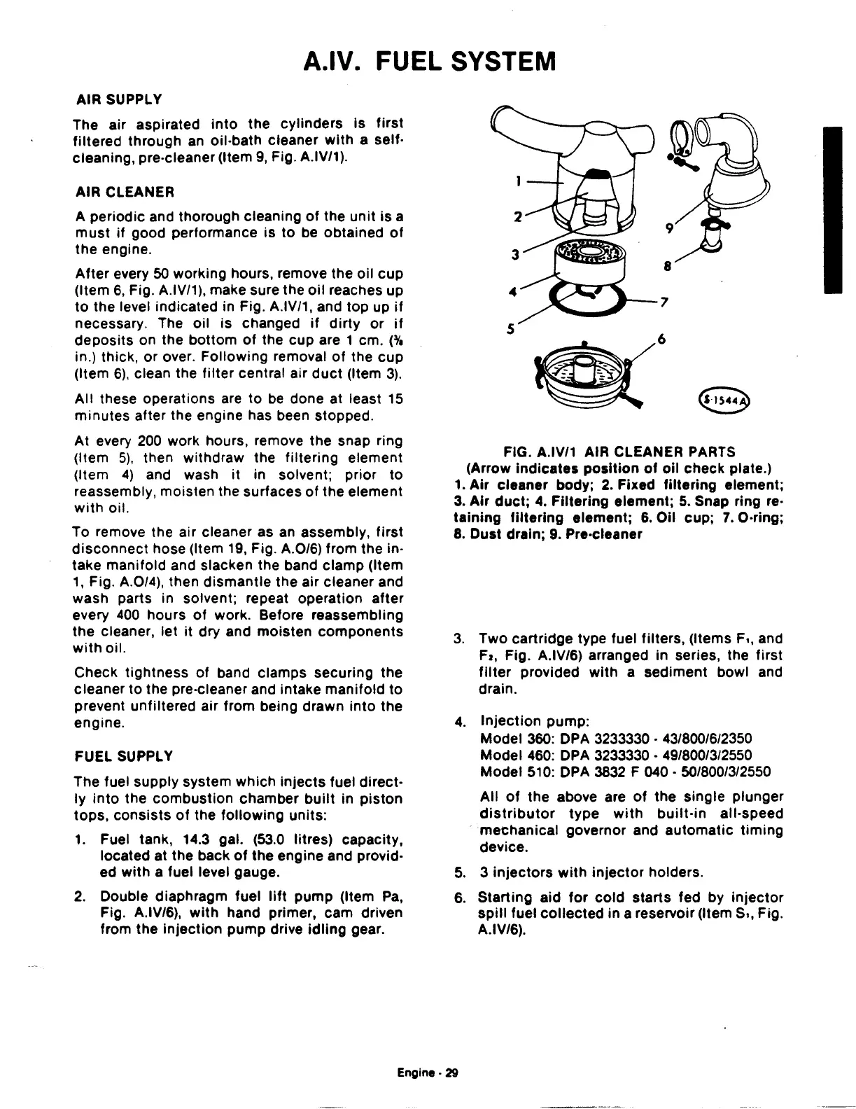
FIG. A.IV/1 AIR CLEANER PARTS
(Arrow
indicates
position
of
oil
check plate.)
1.
Air
cleaner body;
2.
Fixed filtering element;
3.
Air
duct;
4.
Filtering element;
5.
Snap ring re·
taining
filtering
element;
6.
Oil cup;
7.
O·ring;
8.
Oust drain; 9. Pre·cleaner
3.
Two
cartridge type fuel filters, (Items F
••
and
Fa,
Fig. A.IV/6) arranged in series, the first
filter
provided
with
a sediment bowl and
drain.
4.
Injection
pump:
Model 360: DPA 3233330 · 43/800/6/2350
Model 460: DPA 3233330 • 49/800/3/2550
Model 510: DPA 3832 F 040 · 50/800/3/2550
All
of
the above are
of
the single plunger
distributor
type
with
built-in
all-speed
mechanical governor and automatic
timing
device.
5.
3
injectors
with
injector
holders.
6.
Starting aid
for
cold
starts
fed by
injector
spill
fuel
collected
in a reservoir
(Items,,
Fig.
A.IV/6).
Engine·
29
 Loading...

