FIG. B.ll/13 TAKING
UP
THE END FLOAT OF
2nd-5th AND 3rd-6th SPEED DRIVE GEAR
NOTE: Arrow shows the retainer dowel
of
planetary gear reduction end plate.
P.
Driver; 42. Driven shaft; 45. Reduction
unit
thrust
ring;
64.
2nd-5th and 3rd-6th speed gear
shifter
bar
scrolls
arranged as shown in Fig.
8.11/13
and
its
retaining pin.
8.
Install the support (Item 23, Fig.
8.11/6)
bar
(Item
19)
with
shifter
fork (Item 20) and the
speed reduction unit engagement
collar
(Item
49).
9.
Install the
transmission
speed selectors and
shifter
bars and forks, as follows:
First, stake punch at three
points
the lower
part
of
the holes
through
selectors and fork
to
prevent the retaining
hollow
pins from fall-
ing out, then arrange them in succession as
shown in the Fig.
8.11/6,
8.11/10
and
8.11/14.
Install the three springs (Item 17, Fig.
8.11/10)
in the housing, place the detent
balls
(Item
16) and make the
shifter
bars
function,
star-
ting
from
either
side and using a punch
to
compress
the springs as illustrated in Fig.
8.11/15.
Fix the selectors and
shifter
fork
to
their
respective bars, by
fitting
the
hollow
pins
with
the
split
side turned as shown in Fig.
8.11114.
10.
Shift
into
two
speed gears simultaneously,
tighten
the driven shaft lock nut (Item
C13,
Fig.
8.11/10),
then install the cover
with
gasket.
11. Place the gasket on the housing
with
the aid
of
grease then install the cover, making sure
that the
lower
end
of
the gearshift lever (Item
C,
Fig.
8.11/14)
fits
in the seat on the planetary
gear
unit
central
selector
(Item 12, Fig.
8.11/14).
In case the speed gear selector mechanism
has been disassembled, reassemble
it
and
60515
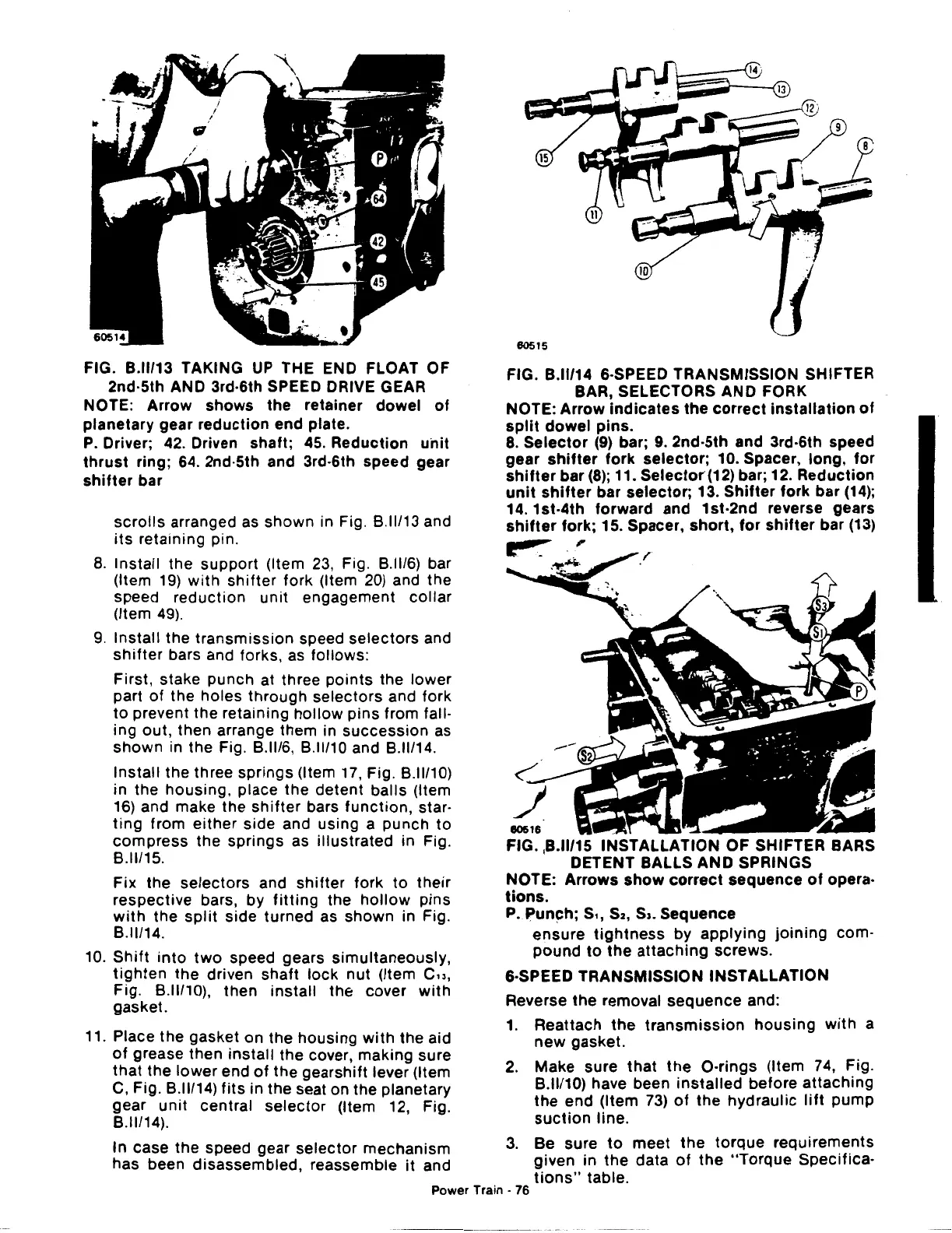
FIG. B.ll/14 &·SPEED TRANSMISSION SHIFTER
BAR, SELECTORS AND FORK
NOTE: Arrow
indicates
the
correct
installation
of
split
dowel
pins.
8.
Selector
(9)
bar;
9.
2nd-5th and 3rd·6th speed
gear
shifter
fork
selector;
10. Spacer, long,
for
shifter
bar
(8);
11.
Selector
(12) bar; 12. Reduction
unit
shifter
bar selector; 13.
Shifter
fork bar
(14);
14. 1st-4th forward and 1st·2nd reverse gears
shifter
fork; 15. Spacer,
short,
for
shifter
bar
(13)
~,
80516
FIG. ,B.II/15 INSTALLATION
OF
SHIFTER BARS
DETENT BALLS
AND
SPRINGS
NOTE: Arrows
show
correct
sequence
of
opera·
tions.
P.
,:»un~h;
s,,
S2,
s,. Sequence
ensure
tightness
by
applying
joining
com-
pound
to
the
attaching
screws.
&·SPEED TRANSMISSION INSTALLATION
Reverse the removal sequence and:
1.
Reattach
the
transmission
housing
with
a
new
gasket.
2.
Make sure
that
the
0-rings
(Item 74, Fig.
B.ll/10) have been
installed
before attaching
the
end (Item 73)
of
the hydraulic
lift
pump
suction
line.
3.
Be sure
to
meet
the
torque
requirements
given in
the
data
of
the
"Torque
Specifica·
tions"
table.
Power Train -
76
 Loading...

