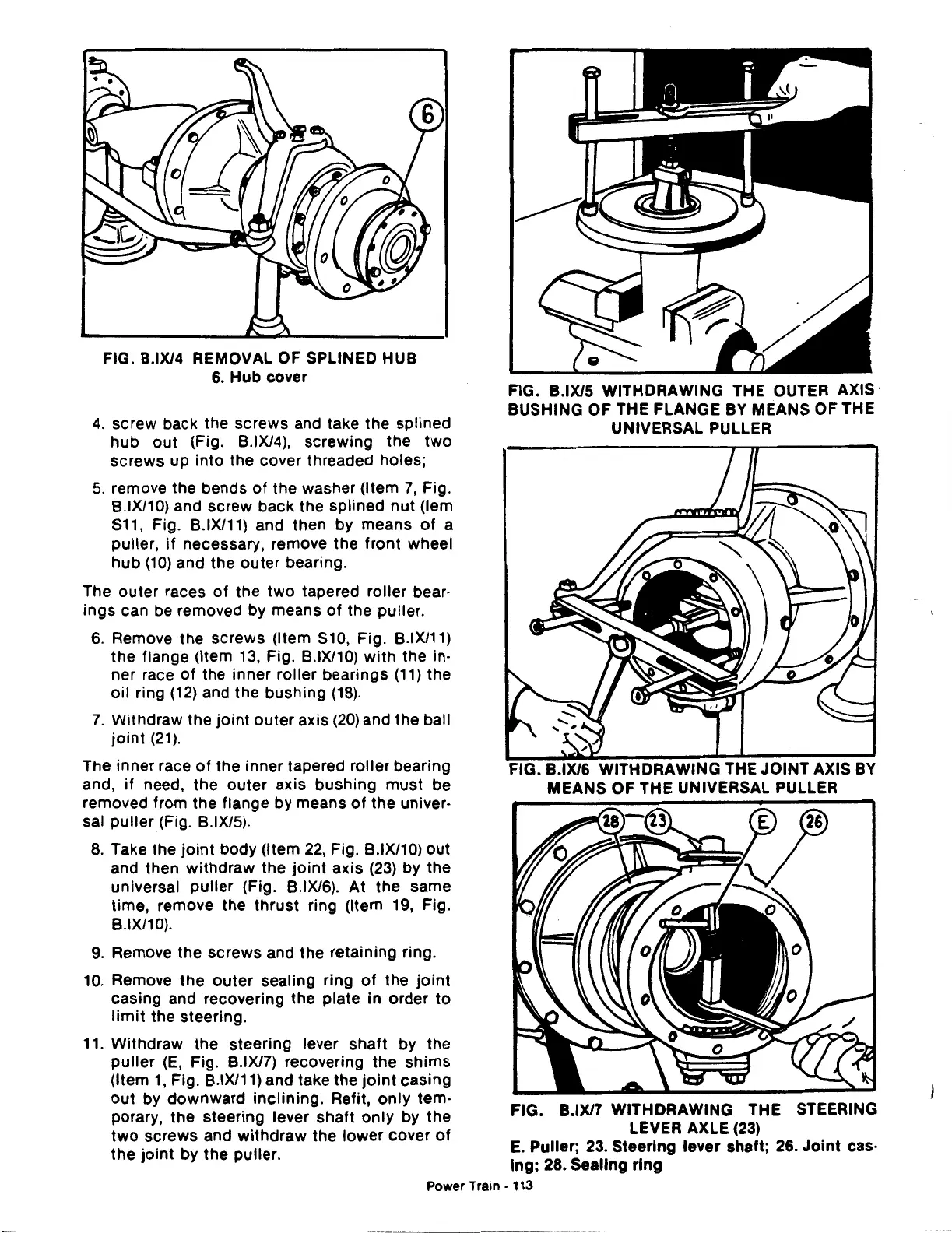
FIG. B.IX/4 REMOVAL OF SPLINED HUB
6.
Hub cover
4.
screw back the screws and take the splined
hub
out
(Fig. B.IX/4),
screwing
the
two
screws
up
into
the cover threaded holes;
5.
remove the bends
of
the washer (Item
7,
Fig.
B.IX/10) and
screw
back
the
splined
nut
(lem
S11, Fig. B.IX/11) and then by means
of
a
puller,
if
necessary, remove the
front
wheel
hub
(10)
and the
outer
bearing.
The
outer
races
of
the
two
tapered roller bear·
ings
can be removed by means
of
the puller.
6.
Remove the screws (Item S10, Fig. B.IX/11)
the flange (Item 13, Fig. B.IX/10)
with
the in·
ner race
of
the inner roller bearings
(11)
the
oil ring
(12)
and the
bushing
(18).
7.
Withdraw the
joint
outer
axis
(20)
and the ball
joint
(21).
The inner race
of
the
inner tapered
roller
bearing
and,
if
need, the
outer
axis
bushing
must
be
removed from the flange by means
of
the univer·
sal
puller
(Fig. B.IX/5).
8.
Take the
joint
body (Item 22, Fig. B.IX/10)
out
and then
withdraw
the
joint
axis
(23)
by the
universal
puller
(Fig. B.IX/6).
At
the
same
time, remove
the
thrust
ring (Item 19, Fig.
B.IX/10).
9.
Remove the
screws
and
the
retaining ring.
10. Remove
the
outer
sealing ring
of
the
joint
casing and recovering
the
plate
in
order
to
limit
the steering.
11. Withdraw
the
steering lever
shaft
by the
puller
(E,
Fig. B.IX/7) recovering
the
shims
(Item
1,
Fig. B.IX/11) and take the
joint
casing
out
by
downward
inclining.
Refit,
only
tern·
porary, the steering lever
shaft
only
by the
two
screws and
withdraw
the
lower
cover
of
the
joint
by
the
puller.
FIG. B.IX/5 WITHDRAWING THE
OUTER
AXIS·
BUSHING OF THE FLANGE
BY
MEANS OF THE
UNIVERSAL PULLER
• B.IX/6 WITHDRAWING THE JOINT AXIS
BY
MEANS OF THE UNIVERSAL PULLER
FIG. B.IX/7 WITHDRAWING THE STEERING
LEVER AXLE
(23)
E.
Puller,
23.
Steering
lever
shaft; 26.
Joint
cas·
ing;
28. Sealing
ring
Power Train • 113
 Loading...

