85293
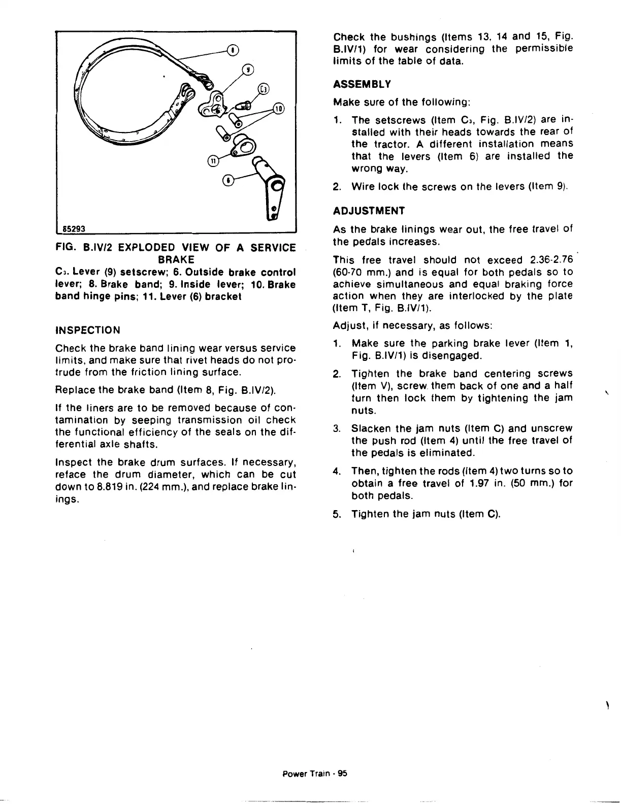
FIG. B.IV/2 EXPLODED VIEW OF A SERVICE
BRAKE
C3.
Lever
(9)
setscrew; 6.
Outside
brake
control
lever;
8.
Brake band;
9.
Inside lever; 10. Brake
band
hinge
pins; 11. Lever
(6)
bracket
INSPECTION
Check the brake band
lining
wear versus service
limits,
and make sure that rivet heads
do
not pro·
trude from the
friction
lining
surface.
Replace the brake band (Item
8,
Fig. B.IV/2).
If the liners are
to
be removed because
of
con-
tamination
by seeping
transmission
oil
check
the
functional
efficiency
of
the seals on the
dif·
ferential axle shafts.
Inspect
the brake drum surfaces. If necessary,
reface the
drum
diameter,
which
can be
cut
down
to
8.819 in. (224 mm.), and replace brake lin-
ings.
Check
the
bushings
(Items
13,
14
and
15,
Fig.
B.IV/1)
for
wear
considering
the
permissible
limits
of
the table
of
data.
ASSEMBLY
Make sure
of
the
following:
1.
The
setscrews
(Item Cl, Fig. B.IV/2) are in·
stalled
with
their
heads towards the rear
of
the
tractor. A
different
installation
means
that
the levers (Item
6)
are
installed
the
wrong way.
2.
Wire
lock
the screws on the levers (Item
9).
ADJUSTMENT
As the brake
linings
wear out, the free travel
of
the
pedals increases.
This free travel should
not
exceed 2.36·2.76
(60·70 mm.) and
is
equal
for
both pedals so
to
achieve
simultaneous
and equal braking force
action
when they are interlocked by the plate
(Item
T,
Fig. B.IV/1).
Adjust,
if necessary, as follows:
1.
Make sure the parking brake lever (Item
1,
Fig. B.IV/1)
is
disengaged.
2.
Tighten
the
brake band centering screws
(Item
V),
screw. them back
of
one and a half
turn
then
lock
them by
tightening
the jam
nuts.
3.
Slacken
the
jam
nuts
(Item C) and unscrew
the
push rod (Item
4)
until
the free travel
of
the
pedals
is
eliminated.
4.
Then,
tighten
the rods (Item
4)
two
turns
so
to
obtain
a free travel
of
1.97 in.
(50
mm.)
for
both
pedals.
5.
Tighten
the jam
nuts
(Item
C).
Power Train · 95
'
 Loading...

