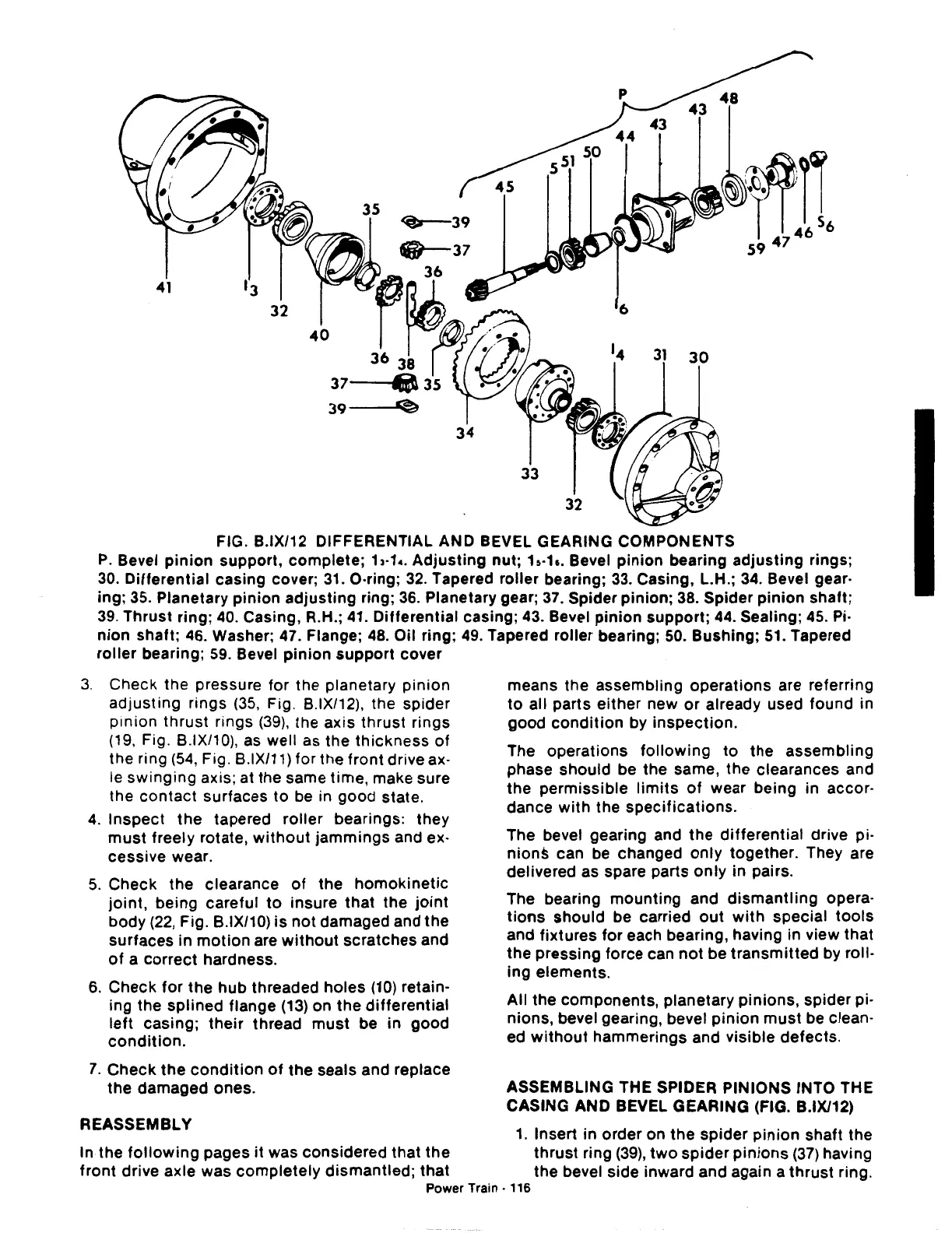
FIG. B.IX/12 DIFFERENTIAL AND BEVEL GEARING COMPONENTS
P.
Bevel
pinion
support,
complete;
13-1
•.
Adjusting
nut;
h·h.
Bevel
pinion
bearing
adjusting
rings;
30.
Differential
casing cover;
31.
0-ring;
32.
Tapered roller bearing;
33.
Casing, L.H.;
34.
Bevel gear-
ing;
35.
Planetary
pinion
adjusting
ring;
36.
Planetary gear;
37.
Spider pinion; 38. Spider
pinion
shaft;
39. Thrust ring; 40. Casing, R.H.; 41. Differential casing; 43. Bevel
pinion
support; 44. Sealing; 45. Pi-
nion
shaft; 46. Washer; 47. Flange;
48.
Oil ring;
49.
Tapered roller bearing;
50.
Bushing;
51.
Tapered
roller
bearing;
59.
Bevel
pinion
support
cover
3.
Check the pressure for the planetary
pinion
adjusting
rings
(35,
Fig. B.IX/12), the spider
pinion
thrust
rings
(39),
the axis thrust
rings
(19, Fig. B.IX/10), as well as the
thickness
of
the ring
(54,
Fig. B.IX/1
1)
for the front drive ax-
le
swinging
axis; at the same time, make sure
the
contact
surfaces
to
be in good state.
4.
Inspect
the
tapered
roller
bearings: they
must
freely rotate,
without
jammings
and ex-
cessive wear.
5.
Check
the
clearance
of
the
homokinetic
joint,
being careful
to
insure
that
the
joint
body
(22,
Fig. B.IX/10)
is
not
damaged and
the
surfaces
in
motion
are
without
scratches
and
of
a
correct
hardness.
6.
Check
for
the
hub
threaded
holes
(10)
retain-
ing
the
splined
flange
(13)
on
the
differential
left
casing;
their
thread
must
be in
good
condition.
7.
Check
the
condition
of
the
seals and replace
the
damaged
ones.
REASSEMBLY
means the assembling operations are referring
to
all parts
either
new
or
already used found in
good
condition
by
inspection.
The operations
following
to
the
assembling
phase should be the same, the clearances and
the permissible
limits
of
wear being in accor-
dance
with
the
specifications.
The bevel gearing and
the
differential
drive pi-
nions
can be changed
only
together. They are
delivered as spare parts
only
in pairs.
The bearing
mounting
and
dismantling
opera-
tions
should be carried
out
with
special
tools
and fixtures
for
each bearing, having in view that
the pressing force can
not
be
transmitted
by roll-
ing elements.
All the components, planetary pinions, spider pi-
nions, bevel gearing, bevel
pinion
must
be clean-
ed
without
hammerings and visible defects.
ASSEMBLING THE SPIDER PINIONS INTO THE
CASING AND BEVEL GEARING (FIG. B.IX/12)
1.
Insert in order on
the
spider
pinion
shaft the
In the
following
pages
it
was considered that
the
thrust
ring
(39),
two
spider
pinions
(37)
having
front
drive axle was
completely
dismantled;
that
the bevel side inward and again a
thrust
ring.
Power
Train-
116

 Loading...
