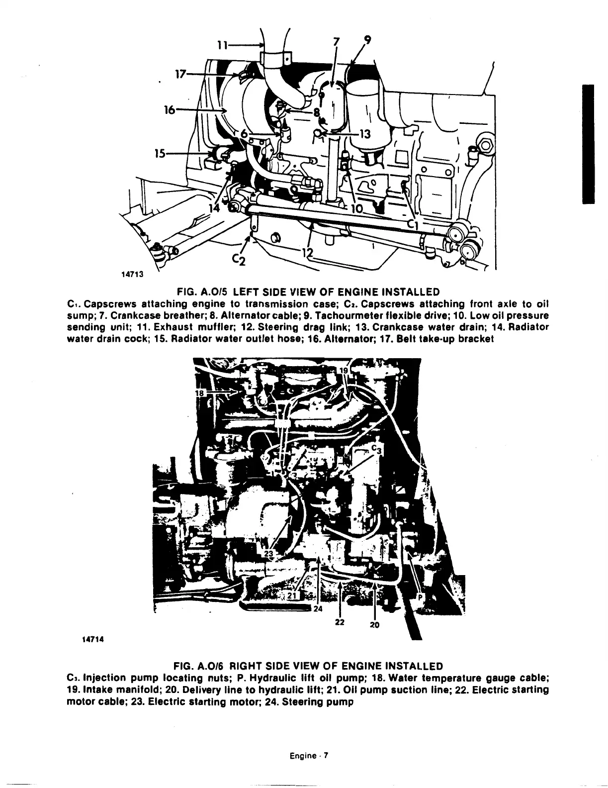
FIG. A.0/5 LEFT SIDE VIEW OF ENGINE INSTALLED
c
..
Capscrews attaching engine
to
transmission case;
C2.
Capscrews attaching front axle
to
oil
sump;
7.
Crankcase breather;
8.
Alternator cable;
9.
Tachourmeter flexible drive;
10.
Low oil pressure
sending unit;
11.
Exhaust muffler; 12. Steering drag link; 13. Crankcase water drain;
14.
Radiator
water drain cock;
15.
Radiator water
outlet
hose; 16. Alternator; 17. Belt take·up bracket
14714
FIG. A.0/6 RIGHT SIDE VIEW OF ENGINE INSTALLED
c,. Injection pump
locating
nuts;
P.
Hydraulic
lift
oil
pump; 18. Water temperature gauge cable;
19. Intake manifold;
20.
Delivery line
to
hydraulic lift;
21.
011
pump
suction
line;
22.
Electric starting
motor
cable;
23.
Electric starting motor;
24.
Steering pump
Engine·
7
 Loading...

