8.11
TRANSMISSION
FIG.
8.11/1
6-SPEED TRANSMISSION GEARS
AND SHAFTS
6-SPEED TRANSMISSION
The transmission (Fig. B.ll/1)
offers
three forward
and one reverse speeds.
The auxiliary planetary gear speed
reduction
unit, arranged at the rear end
of
the
transmission
driven gear shaft,
doubles
the range
of
available
speeds so that the
tractor
offers
six
forward and
two
reverse speeds.
All transmission and planetary gear
unit
gears
have straight teeth.
The driving gears (Item
31,
Fig.
8.1117)
and the
driven ones (Items 63 and
57,
Fig.
8.1118)
of
the
5th and 6th speeds (2nd and 3rd low) are in cons-
tant mesh and speed engagement
is
aided by a
synchromesh device (Item
A,
Fig. B.ll/7).
This device, though being
of
the
conventional
free-cone type, has three flat
outer
springs
(Item
60,
Fig.
8.1118
and B.ll/12) arranged in
suitable
holders (Item
61)
and
applying
a radial force upon
the synchromesh tapered rings (Item
58).
Conse-
quently,
the
axial
mating
of
the cones (Item
58)
over
their
respective tapered
surfaces
in
the
driven gears (Items
57
and 63), brakes
down
the
speed
of
the
latter
thus
synchronizing
it
with
that
of
the fixed sleeve (Item
59)
thus
facilitating
the
quick
engagement
of
the
sliding
collar
(Item 62)
with
the
tractor
in
motion
at
different
engine
speeds.
The engagement
of
the 4th forward speed and
of
the 2nd reverse one (1st forward and 1st reverse
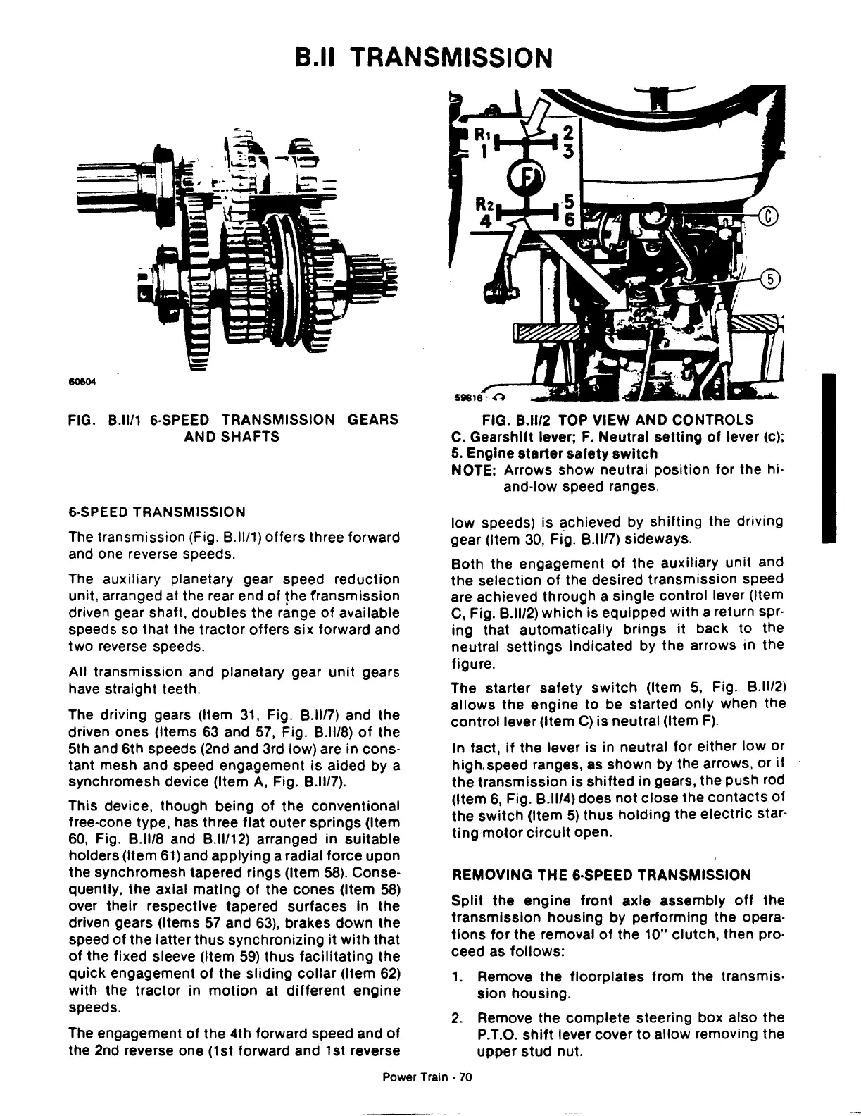
FIG.
8.11/2
TOP VIEW AND CONTROLS
C. Gearshift lever;
F.
Neutral
setting
of
lever (c);
5.
Engine
starter
safety
switch
NOTE: Arrows
show
neutral
position
for
the hi·
and-low speed ranges.
low
speeds) is achieved by
shifting
the driving
gear (Item
30,
Fi.g.
B.ll/7) sideways.
Both
the engagement
of
the auxiliary unit and
the
selection
of
the desired
transmission
speed
are achieved
through
a
single
control lever (Item
C, Fig.
8.11/2)
which
is equipped
with
a return spr-
ing that
automatically
brings
it
back
to
the
neutral
settings
indicated
by the arrows in the
figure.
The
starter
safety
switch
(Item
5,
Fig. B.ll/2)
allows
the
engine
to
be started
only
when the
control
lever (Item
C)
is
neutral (Item
F).
In fact,
if
the lever
is
in neutral
for
either
low
or
high. speed ranges, as shown by the arrows, or
if
the
transmission
is
shifted
in gears, the push rod
(Item
6,
Fig.
8.1114)
does
not
close
the
contacts
of
the
switch
(Item
5)
thus
holding
the
electric
star-
ting
motor
circuit
open.
REMOVING THE &·SPEED TRANSMISSION
Split
the
engine
front
axle
assembly
off
the
transmission
housing
by
performing
the opera-
tions
for
the
removal
of
the
10"
clutch,
then pro-
ceed as
follows:
1.
Remove
the
floorplates
from
the transmis-
sion
housing.
2.
Remove
the
complete
steering box also the
P.T.O.
shift
lever cover
to
allow
removing the
upper
stud
nut.
Power Train -
70
 Loading...

