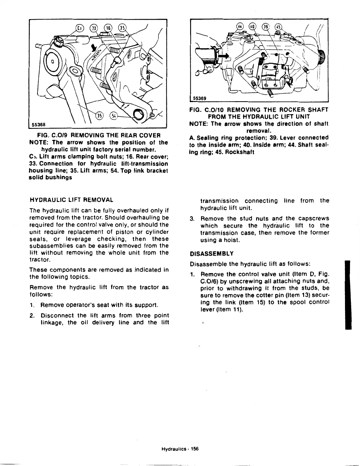
FIG.
C.0/9
REMOVING THE REAR COVER
NOTE: The arrow
shows
the
position
of
the
hydraulic
lift
unit
factory serial number.
C3.
Lift
arms
clamping
bolt
nuts; 16. Rear cover;
33.
Connection
for
hydraulic
lift-transmission
housing
line;
35.
Lift
arms;
54.
Top
link
bracket
solid
bushings
HYDRAULIC LIFT REMOVAL
The
hydraulic
lift
can be fully overhauled
only
if
removed from the tractor. Should overhauling be
required
for
the
control
valve only,
or
should the
unit
require replacement
of
piston
or
cylinder
seals,
or
leverage
checking,
then
these
subassemblies
can be easily removed from the
lift
without
removing the whole
unit
from the
tractor.
These
components
are removed as indicated in
the
following
topics.
Remove the hydraulic
lift
from the
tractor
as
follows:
1.
Remove operator's seat
with
its
support.
2.
Disconnect
the
lift
arms from three
point
linkage, the
oil
delivery line and the
lift
FIG. C.0/10 REMOVING THE ROCKER SHAFT
FROM THE HYDRAULIC LIFT UNIT
NOTE: The arrow
shows
the
direction
of
shaft
removal.
A. Sealing ring
protection;
39. Lever
connected
to
the
inside
arm; 40. Inside arm; 44. Shaft seal·
lng
ring; 45. Rockshaft
transmission
connecting
line
from
the
hydraulic
lift
unit.
3.
Remove the
stud
nuts
and the
capscrews
which
secure the
hydraulic
lift
to
the
transmission
case,
then
remove the
former
using
a
hoist.
DISASSEMBLY
Disassemble the
hydraulic
lift
as
follows:
1.
Remove
the
control
valve
unit
(Item
D,
Fig.
C.0/6) by
unscrewing
all
attaching
nuts
and,
prior
to
withdrawing
it
from
the
studs,
be
sure
to
remove the
cotter
pin (Item 13) secur·
ing
the
link
(Item 15)
to
the
spool
control
lever (Item
11
).
Hydraulics·
156
 Loading...

