RECTIFYING DIODES
The diodes are used
to
rectify the alternator out·
put
into
direct current
to
charge the battery.
The diode rectifiers for the
1100
series alter-
nators are silicon units.
The covering
of
the diode is one
of
the
two
elec-
trical terminals. The other terminal consists
of
a
flexible conductor, the end
of
which has a cable
shoe. The diode
is
positive when the flexible
conductor
is
of
positive polarity and the case
of
negative polarity. The negative diodes allow the
current
to
pass only in reverse direction (from
case
to
flexible conductor).
When
this
test
is
to
be
carri~d
out, insert a bulb
between the source of voltage and the diode.
This bulb is necessary
to
limit
the current
to
a
rated value of less than 25A, because short-
circuit
currents
might
destroy the diode.
The diode rectifier unit is connected according
to
the wiring diagram of Fig. 0.119-known
as
a
3-phase
bridge-and
consists
of
three positive
diodes and three negative diodes.
DIODE SPECIFICATIONS:
-Max.
direct current
....................
25
A
-Continuous
max. reverse voltage
........
75
V
-Max.
peak reverse voltage
.............
200
V
-Max.
operating temperature
..
+ 300°F.( +
150°C)
+
p
FIG. D.l/9 WIRING DIAGRAM OF THE 3-PHASE
BRIDGE-CONNECTED RECTIFIER
G. Alternator;
P.
3·phase rectifier bridge.
INSTRUCTIONS FOR CHECKING DIODES
To check the
efficiency
of
the rectifier unit, be
sure that the single diodes do not have the
following failures:
-open-in
this case, they will not allow the flow
of
current to pass in either direction.
-short-circuited-in
this case, the diode allows
the current
to
flow
in both directions.
The rectifier diodes can be checked without
removing them from the Alternator.
Just
discon-
nect
the flexible conductor terminals from the
screws that attach them
to
the phase terminals,
to
the diode-holder bracket plate as shown in
Fig.
0.1110.
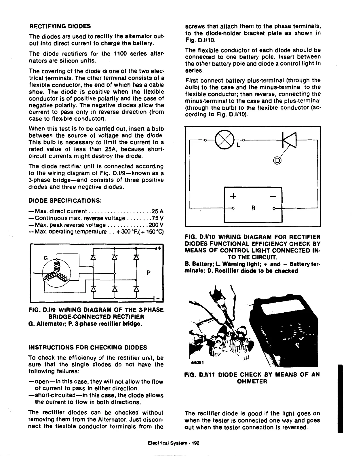
The flexible conductor
of
each diode should be
connected
to
one battery pole. Insert between
the other battery pole and diode a control
light
in
series.
First connect battery plus-terminal (through the
bulb)
to
the
case and the minus-terminal
to
the
flexible conductor; then reverse, connecting the
minus-terminal
to
the case and the plus-terminal
(through the bulb)
to
the flexible conductor (ac-
cording
to
Fig.
0.1/10).
L
+
B
FIG. D.l/10 WIRING DIAGRAM
FOR
RECTIFIER
DIODES FUNCTIONAL EFFICIENCY CHECK
BY
MEANS OF CONTROL LIGHT CONNECTED IN·
TO
THE CIRCUIT.
B. Battery;
L.
Warning light; + and - Battery ter·
mlnals;
D.
Rectifier diode
to
be checked
FIG. D.l/11 DIODE CHECK BY MEANS OF AN
OHMETER
The
rectifier
diode is good
if
the light goes on
when the tester
is
connected one way and goes
out
when the tester connection
is
reversed.
Electrical System •
192
 Loading...

