5
6
3
4
1
Jl
/
,..
,..
,..
/
,..
,..
/
,..
,..
20
,..
I
,.."'
15
16
:
~/~/
I
,..~
l
1/"'
18
17
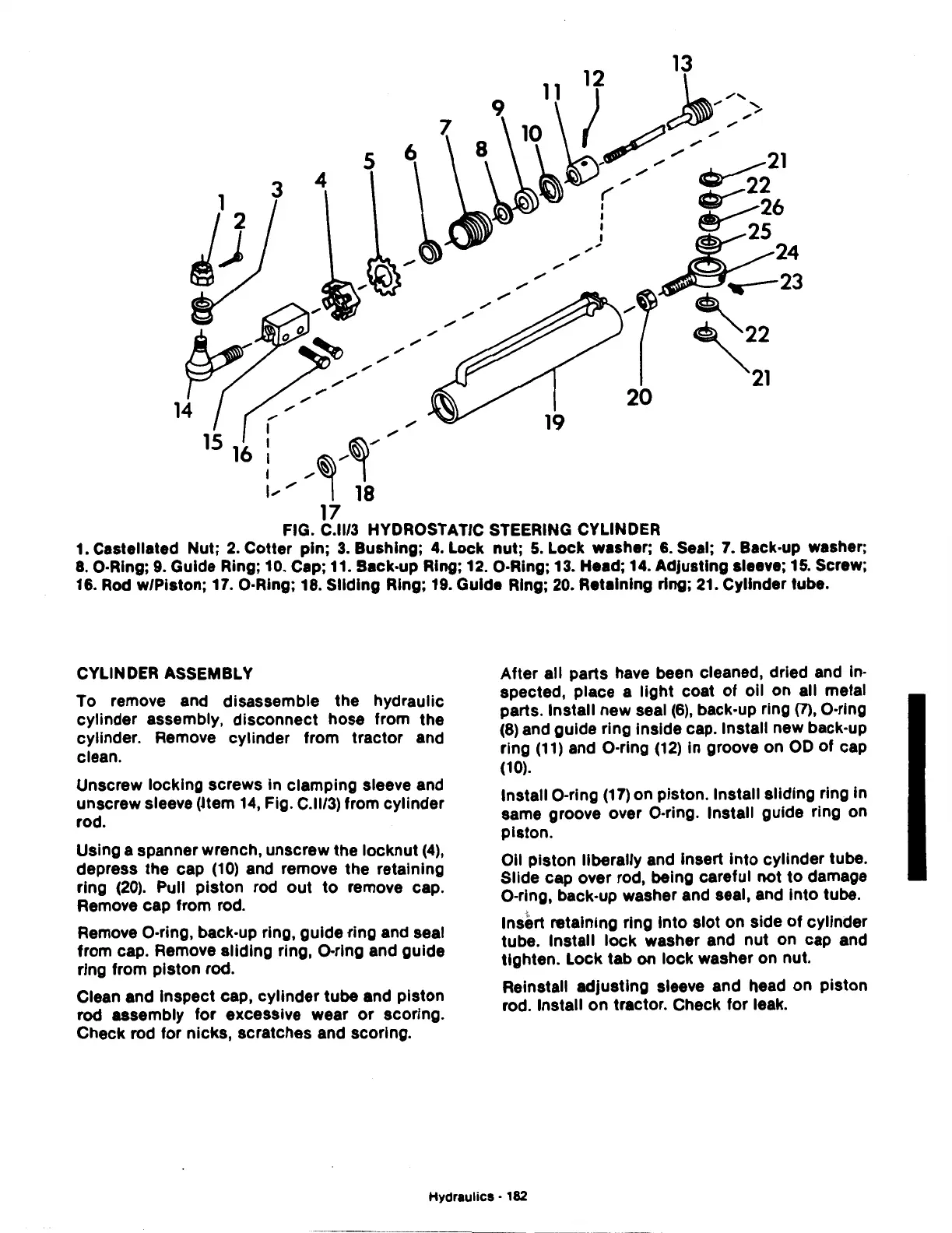
FIG. C.ll/3 HYDROSTATIC STEERING CYLINDER
1.
Castell~ted
Nut;
~·Cotter
pin;
3.
Bushing;
4.
Lock nut;
5.
Lock washer;
6.
Seal;
7.
Back-up washer;
8.
O·Ring,
9.
Guide Rmg;
~0.
Cap;
11.
Back-up Ring; 12. O·Ring; 13. Head; 14. Adjusting sleeve;
15.
Screw;
16.
Rod
w/Piston; 17. O·Rmg; 18. Sliding Ring; 19. Guide Ring;
20.
Retaining ring;
21.
Cylinder tube.
CYLINDER ASSEMBLY
To.
remove and disassemble the hydraulic
cylinder assembly, disconnect hose from the
cylinder. Remove cylinder from tractor and
clean.
Unscrew locking screws in clamping sleeve and
unscrew sleeve
(Jtem
14,
Fig. C.ll/3) from cylinder
rod.
Using a spanner wrench, unscrew the locknut
(4),
depress the cap
(10)
and remove the retaining
ring
(20).
Pull piston rod
out
to
remove cap.
Remove cap from rod.
Remove O·ring, back-up ring, guide ·ring and seal
from cap. Remove sliding ring, 0-ring and guide
ring from piston rod.
Clean and Inspect cap, cylinder tube and piston
rod assembly for excessive wear
or
scoring.
Check rod for nicks, scratches and scoring.
After all parts have been cleaned, dried and in-
spected, place a light coat
of
oil on all metal
parts. Install new seal
(6), back-up ring (7), 0-ring
(8) and guide ring inside cap. Install new back-up
ring
(11)
and 0-ring
(12)
in groove on
OD
of cap
(10).
Install 0-ring
(17)
on piston. Install sliding ring in
same groove over O·ring. Install guide ring on
piston.
Oil piston liberally and insert
into
cylinder tube.
Slide cap over rod, being careful not
to
damage
0-ring, back-up washer and seal, and into tube.
Insert retaining ring Into slot on side
of
cylinder
tube. Install lock washer and nut on cap and
tighten. Lock tab on lock washer on nut.
Reinstall adjusting sleeve and head on piston
rod. Install
on
tractor. Check for leak.
Hydraulics •
182

 Loading...
