COPY IMAGE ADJUSTMENTS: PRINTING/SCANNING
SM 3-143 B064 Series/B140 Series/G126
Replacement
Adjustment
3.14 COPY IMAGE ADJUSTMENTS: PRINTING/SCANNING
These adjustments must be performed after replacing any of the following parts:
• Scanner wires
• Lens block
• Scanner motor
• Polygon motor
• Tandem tray side fences
• Memory All Clear
3.14.1 PRINTING
1. Make sure paper is installed correctly in each paper tray before you start these
adjustments.
2. Use the Trimming Area Pattern (SP2-902-3, No. 18 to print the test pattern for
the following procedures.
3. After completing these printing adjustments, be sure to set SP 2-902-3 to 0
again.
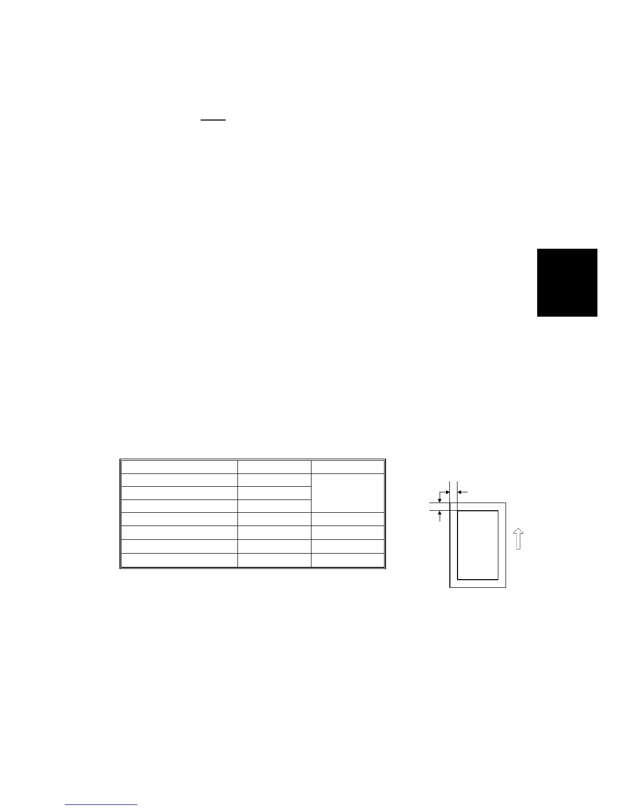
Registration - Leading Edge/Side-to-Side
1. Check the leading edge registration, and adjust it using SP1-001.
Specification: 3 ± 2mm.
2. Check side-to-side registration for each paper feed station, and adjust with the
following SP modes.
SP mode Specification
Tray 1 (Tandem Tray) SP1002-001
Tray 2 (Universal Tray) SP1002-002
Tray 3 (Universal Tray) SP1002-003
0±1.5
Tray 4 SP1002-004 Japan Only
By-pass Tray SP1002-005
0±1.5
LCT SP1002-006
0±1.5
Duplex Tray SP1002-007
0±1.5
B
A
B140R887.WMF
 Loading...