118
Fader Bank Section
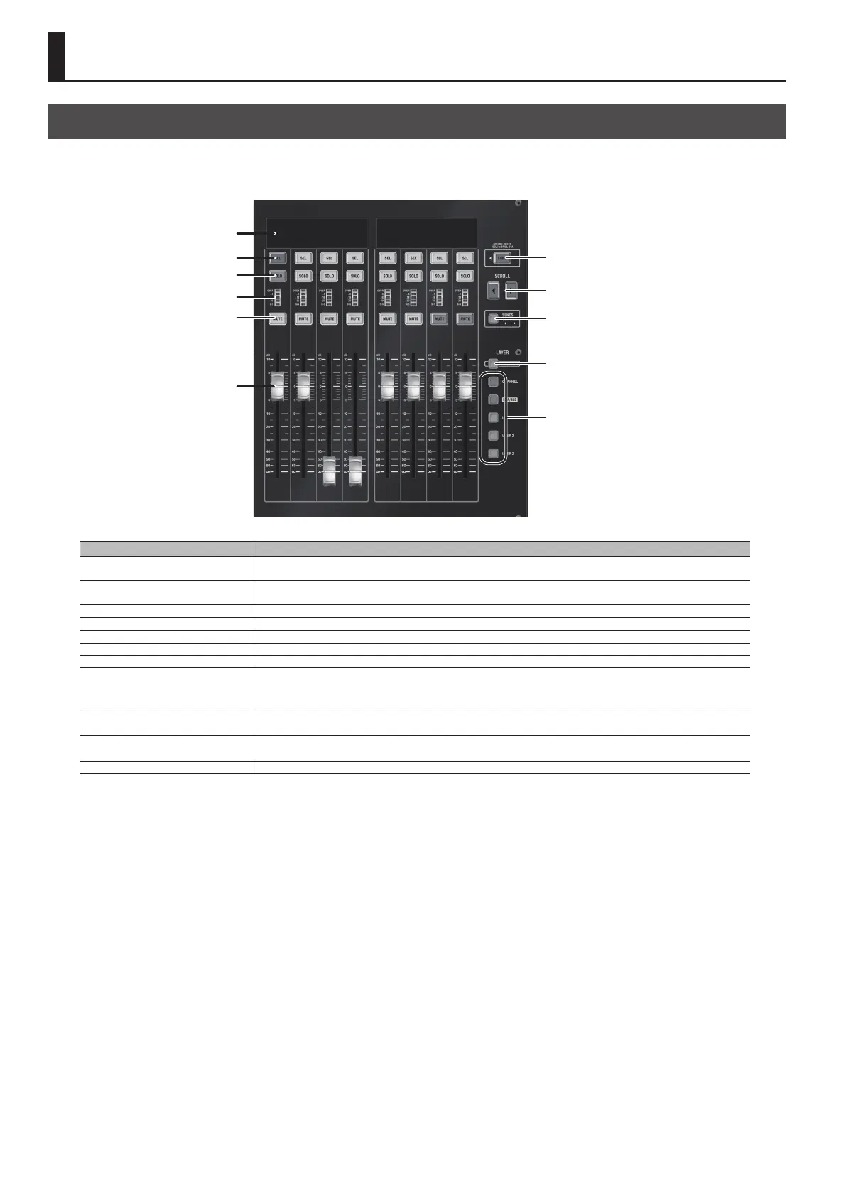
About the Fader Bank Section
On the M-5000, operations are carried out using groups of eight faders. Each set of eight faders is called a “fader bank.”
The M-5000 provides three fader banks. You can operate the respective fader banks in an interlinked way or independently, enabling you to carry out
your intended operations instantly.
Fader Bank display
[SEL] button
[FUNC] button
[SCROLL K] /
[SCROLL J] button
[SENDS ON FADER] button
[ISOLATE] button
Layer buttons
[SOLO] button
Level meter
[MUTE] button
Fader
Name Description
Fader bank display
This displays information such as the input channel/output bus name and fader value. In the Function mode, it displays
a list of functions and parameter values.
[SEL] button
This selects the input channel/output bus and selects the display target. In the Function mode, it selects the function
and manipulates parameters.
[SOLO] button This turns solo on and o for the input channel/output bus.
Level meter This displays the signal level of the input channel/output bus.
[MUTE] button This turns muting on and o for the input channel/output bus.
Fader This operates the fader for the input channel/output bus.
[FUNC] button This turns the function mode on and o. It ashes when the function mode is on.
[SCROLL K] /
[SCROLL J] button
(JUMP)
This scrolls the channel left and right.
Pressing [SCROLL <] and [SCROLL >] at the same time displays the anchor channel where the currently selected Layer in
the fader bank display is registered (anchor jump).
[SENDS ON FADER] button
This turns SENDS ON FADER on and o. It ashes when on.
0“Using Faders to Adjust the Send Level to AUX (SENDS ON FADER)” (p. 122)
[ISOLATE] button
This turns isolate of Fader Bank on and o.
0“Isolated Banks” (p. 120)
Layer buttons This selects the layer for the Fader Bank section. The button for the selected layer lights up.
 Loading...