Part Names and Functions
42
15 WORD CLOCK IN/OUT Connectors
These are connectors for word-clock input and output. To terminate
word-clock input at the M-5000, set the 75 ohms switch to ON.
16 BATTERY Slot
This slot contains a lithium battery that maintains the M-5000’s
clock function and preserves the mixer settings. If the battery runs
down, you need to replace it.
0“Replacing the Internal Lithium Battery” (p. 22)
17 Ground Terminal
This terminal is used to connect the M-5000 to an electrical ground.
* Depending on the circumstances of a particular setup, you
may experience a discomforting sensation, or perceive that
the surface feels gritty to the touch when you touch this
device, microphones connected to it, or the metal portions of
other objects, such as guitars. This is due to an innitesimal
electrical charge, which is absolutely harmless. However, if
you are concerned about this, connect the ground terminal
(see gure) with an external ground. When the unit is grounded,
a slight hum may occur, depending on the particulars of your
installation. If you are unsure of the connection method, contact
the nearest Roland Service Center, or an authorized Roland
distributor, as listed on the “Information” page.
Unsuitable places for connection:
5 Water pipes (may result in shock or electrocution)
5 Gas pipes (may result in re or explosion)
5 Telephone-line ground or lightning rod (may be dangerous in
the event of lightning)
18 AC INPUT Connector, Power-cord Clamp
This connector is for attaching the included power cord.
To keep the power cord from being inadvertently disconnected,
you use the power-cord clamp to secure the cord in place.
0“Connecting the Power Cord” (p. 16)
0“Using the Power-cord Clamp” (p. 16)
19 Power-cord Hook
You can use this power cord hook to prevent the power cord from
being accidentally disconnected.
0“Using the Power-cord Hook” (p. 18)
20 Cooling Fan
This is the fan for cooling the M-5000. When placing the M-5000, be
careful not to obstruct the ventilation holes.
21 EXT. POWER DC INPUT Connector
This connector is for attaching an optional S-240P external power-
supply unit to supply backup power to the M-5000.
If an S-240P External Power Supply Unit is providing power to the
M-5000, the M-5000 will keep operating even if the power switch is
in the OFF position.
* DC INPUT [DC+24V / 6A]
NOTE
To avoid damage or injury, never connect anything to the EXT.
POWER DC INPUT jack except the DC output of the S-240P
External Power Supply Unit.
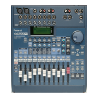
22 OUTPUT 1–16 Connectors (M-5000 only)
These are male balanced XLR-3-32 output connectors for sending
analog audio signals.
* Make connections after rst checking the wiring diagrams of
other equipment you intend to connect.
HOT
COLD
GND
1 2
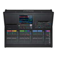
23 OUTPUT 1–8 Connectors (M-5000C only)
These are male balanced XLR-3-32 output connectors for sending
analog audio signals.
* Make connections after rst checking the wiring diagrams of
other equipment you intend to connect.
HOT
COLD
GND
1 2
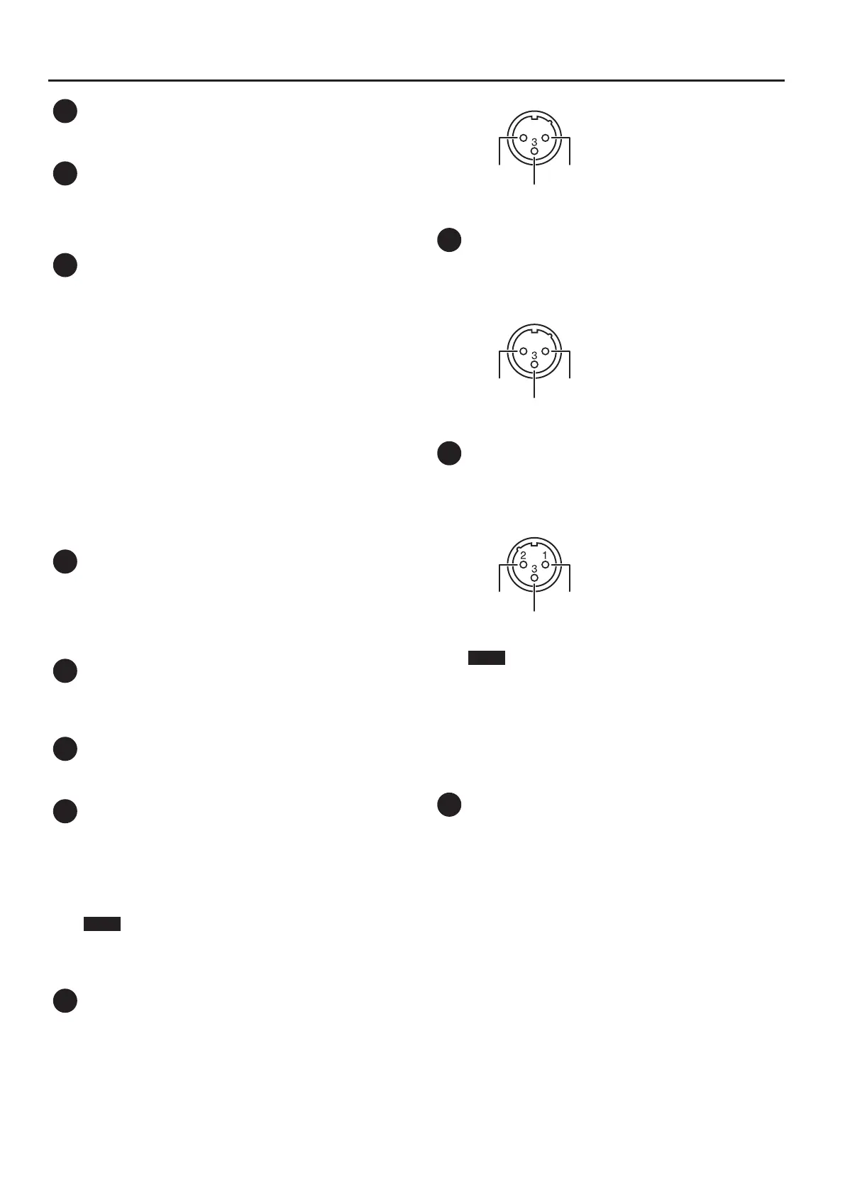
24 INPUT 1–16 Connectors
These are female balanced XLR-3-31 input connectors for incoming
analog audio signals from microphones and line-level equipment.
* Make connections after rst checking the wiring diagrams of
other equipment you intend to connect.
GND
+PHANTOM [+48V/14mA]
COLD
HOT
NOTE
Always turn the phantom power o when connecting any
device other than condenser microphones that require
phantom power. You risk causing damage if you mistakenly
supply phantom power to dynamic microphones, audio
playback devices, or other devices that don’t require such
power. Be sure to check the specications of any microphone
you intend to use by referring to the manual that came with it.
(This instrument’s phantom power: DC+48 V, 14 mA Max)
25 EXPANSION SLOT
This slot is for installing an optional expansion interface.
* When restarting the unit with the expansion interface installed,
wait for about one second before you turn on the power.
0“Installing an Expansion Interface (Option)” (p. 24)
 Loading...