250
GP I/O and Foot Switches
You use the GP I/O connector and the FOOT SW 1 and 2 jacks to
send and receive control signals to and from external devices.
Function List
Functions Assignable to GPI Connectors and
FOOT SW 1/2 Jacks
RECALL SCENE This recalls the specied scene.
PREV SCENE
This recalls the scene previous to the currently
selected scene.
NEXT SCENE
This recalls the next scene after the currently
selected scene.
TALK This turns talkback on or o.
BLINK TALK
This makes the LED for the [TALK] button ash for
the specied length of time.
DIM MONITOR This turns the monitor dimmer on or o.
TAP DELAY
This enables inputting the delay time for the
specied FX by tapping.
AUDIO FOLLOW
VIDEO
This operates the specied fader to the specied
two values.
FADER LEVEL
This operates the specied fader.
(Speciable value range; GPI connector only)
Functions Assignable to GPO Connectors
SCENE RECALL This outputs a pulse signal during scene recall.
TALK
This outputs a continuous signal when talkback
is on.
FADER START
This outputs a pulse signal when the specied
fader exceeds a specied value.
FADER STOP
This outputs a pulse signal when the specied
fader falls below a specied value.
FADER ON
This outputs a continuous signal from when the
specied fader exceeds the “on” level until it falls
below the “o” level.
USER BUTTON
This outputs a continuous signal when the
specied user-assignable button (button [
1
]
--- [8]) is on.
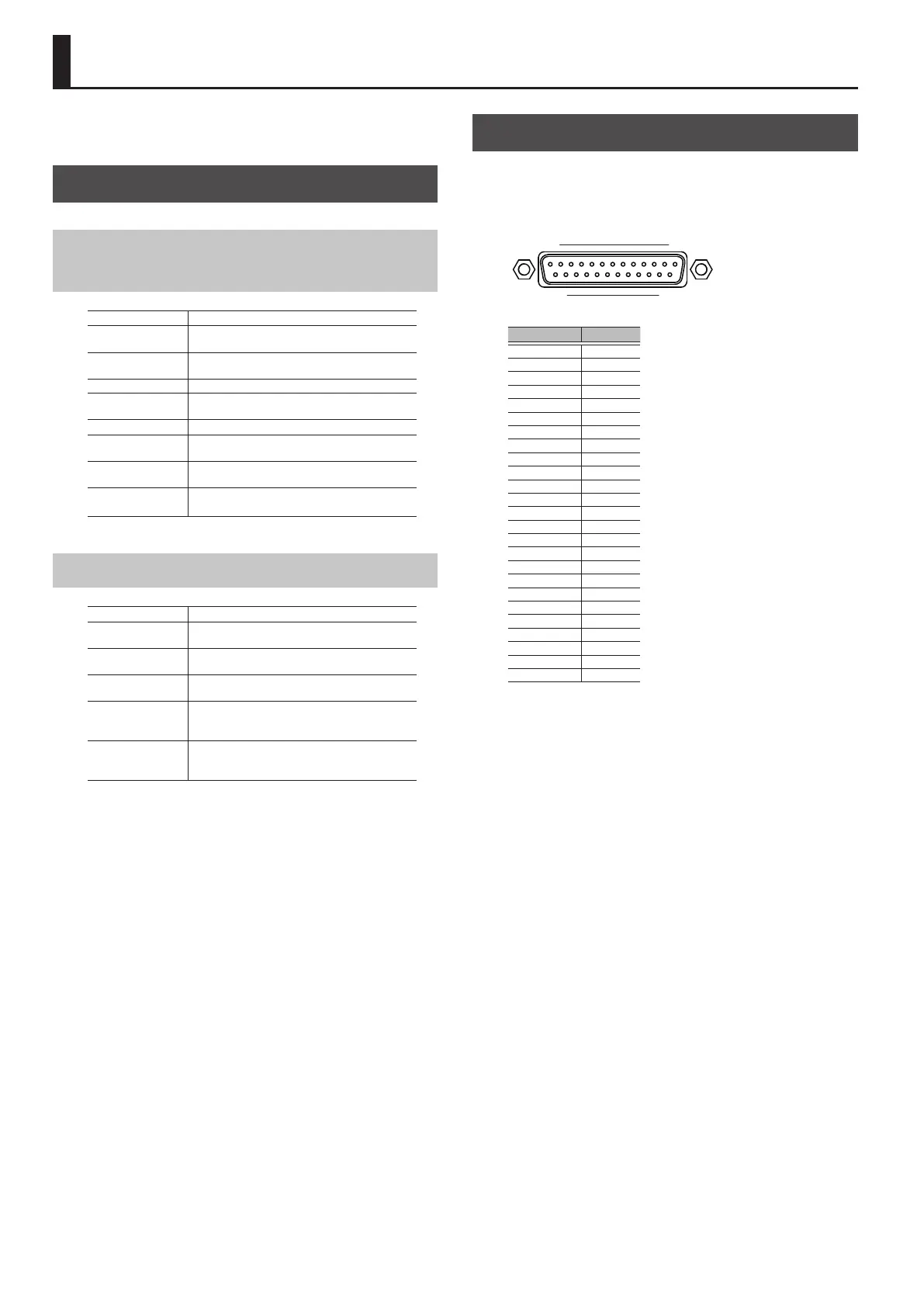
GP I/O Connector Hardware Specications
GP I/O Connector
This is a D-sub 25-pin connector (4 in/12 out) for sending and
receiving control signals to and from an external device.
113
1425
Connector No. Type
1 GPO 1
2 GPO 3
3 GPO 5
4 GPO 7
5 GND
6 GND
7 GND
8 GND
9 +5V
10 GPI 2
11 GPI 4
12 GPO 10
13 GPO 12
14 GPO 2
15 GPO 4
16 GPO 6
17 GPO 8
18 GND
19 GND
20 GND
21 +5V
22 GPI 1
23 GPI 3
24 GPO 9
25 GPO 11
Input pin [Voltage detection range: 0-5V , Max +5V]
Output pin [Open collector , Vmax=12V , Imax/pin=75 mA]
DC OUTPUT [DC+5V / 1000mA]
 Loading...