Home
Roland
Music Mixer
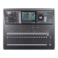
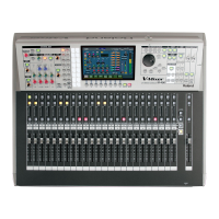
M-5000
Roland M-5000 Reference Manual
4
of 1
of 1 rating
276 pages
Give review
Manual
Specs
To Next Page
To Next Page
To Previous Page
To Previous Page
Loading...
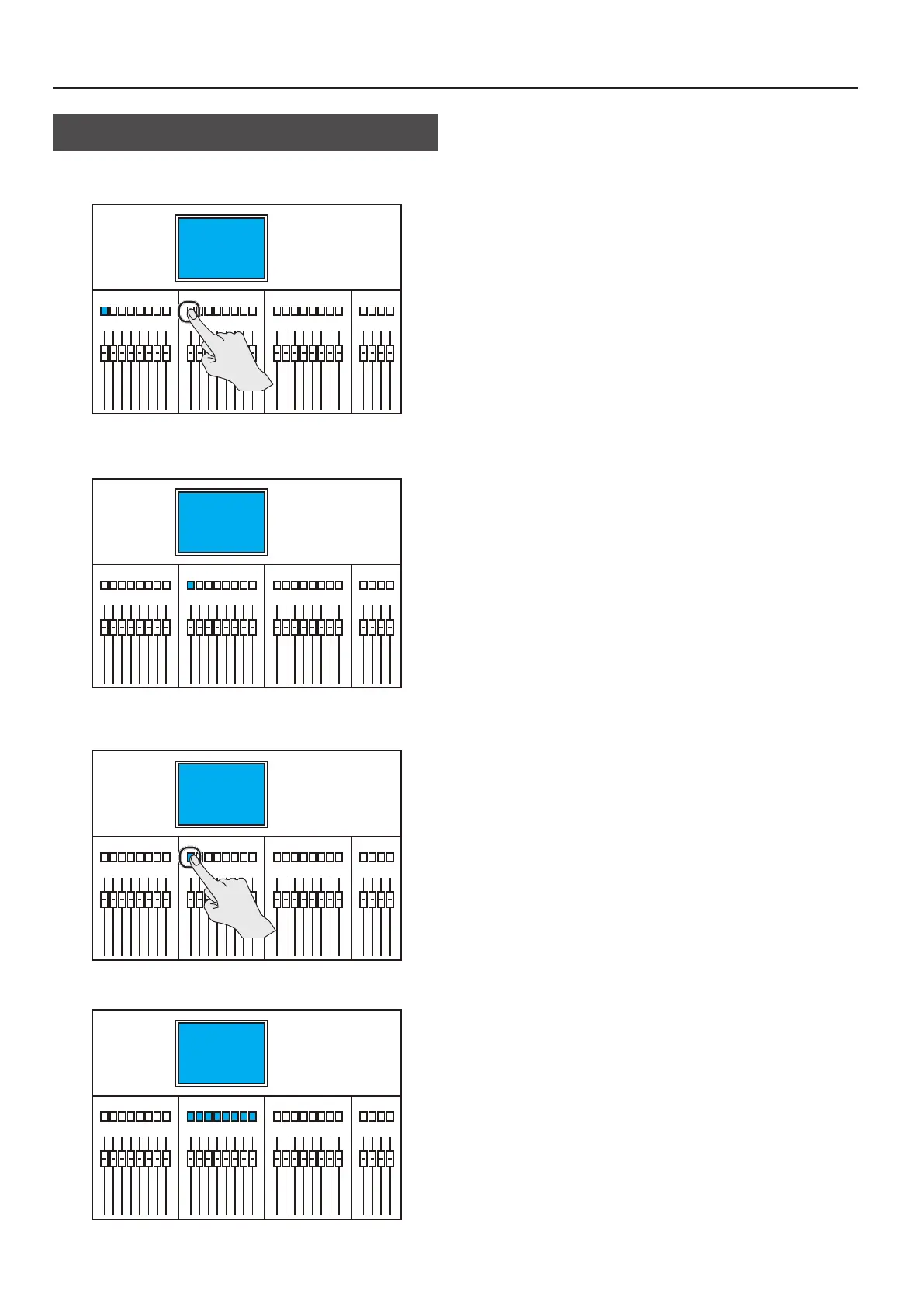
Switching the HOME Scr
een/CH EDIT Screen
130
When the CH EDIT Scr
een Is Display
ed
1.
Press an unselected [SEL] button.
The CH EDIT window for the selected input channel or output bus
appears.
2.
Press the selected [SEL] button.
The CH EDIT window disappears and the HOME screen appears
.
129
131
Table of Contents
Default Chapter
2
Default Chapter
2
Organization of the Documentation
2
Table of Contents
3
Main Features
10
Update History
13
Ver.1.101
13
Ver.1.020
13
Ver.1.001
13
Quick Start
14
Placement and Setup
15
Included Items
15
Attaching the Ferrite Cores
15
Detaching the USB Cover (M-5000C Only)
15
Detaching the REAC Caps
16
Attaching the REAC Connector Covers
16
Connecting the Power Cord
16
Using the Power-Cord Clamp
16
Retrait des Caches REAC
17
Fixation des Couvres Connecteur REAC
17
Connexion du Cordon D'alimentation
17
Utilisation de L'attache du Cordon D'alimentation
17
Using the Power-Cord Hook
18
Connecting Backup Power to the M-5000
18
Utilisation du Crochet du Cordon D'alimentation
19
Raccordement D'une Alimentation de Secours au M-5000
19
Disconnecting Backup Power
20
Turning the Power on and off
20
Turning the Power off
20
Turning the Power on
20
Déconnexion de L'alimentation de Secours
21
Mise Sous Tension et Hors Tension de L'appareil
21
Mise Hors Tension
21
Mise Sous Tension
21
Replacing the Internal Lithium Battery
22
Attaching the Tablet Sheets
22
Remplacement de la Pile au Lithium Interne
23
Fixation des Housses de Tablette
23
Installing an Expansion Interface (Option)
24
Using the LAN-Cable Hook
24
Installation D'un Module D'interface (en Option)
25
Utilisation du Crochet de Câble Réseau
25
Installing REAC Devices
26
Basic REAC Knowledge
26
About Cables
26
Ethernet Cable Types
26
Ethernet Connectors
26
Important Notes on Handling Ethernet Cables
26
Connecting REAC Input/Output Units
27
Important Notes on REAC Connections
27
Part Names and Functions
28
Top Panel
28
Talkback Section
29
Fader Bank Section
30
Assignable Fader Section
31
USB MEMORY Connector
31
Display Section
32
Monitor Section
33
Recorder Section
34
Scene Section
34
Talkback Section
35
User-Assignable Section
36
Rear Panel
38
Panneau Arrière
39
MIDI Connectors
40
Ground Terminal
42
Front Panel
44
Panneau Avant
45
Overview of Operations
46
Fader Bank Section
46
Layers
46
Scrolling
46
Basic Operations of Fader Bank Section
46
Changing Layers
46
Scrolling the Channels
46
Anchor Channels
47
Accessing an Anchor Channel (Anchor Jump)
47
Accessing Adjacent Anchor Channels
47
Isolated Banks
48
Isolating a Fader Bank
48
Unisolating a Fader Bank
48
Basic Touch Operations
49
Using Templates to Select a Mixer Configuration
49
HOME Screen
50
Access the CH EDIT Window
50
Selecting the Source for an Input Channel
51
Selecting the Destination for an Output Bus
51
Turning Phantom Power on or off
52
Adjusting the Preamp Gain
52
Applying Dynamics
53
Applying EQ
53
Using Faders to Adjust the Send Level to aux (SENDS on FADER)
53
Sending to SUBGROUP/MIX-MINUS
54
Using an FX with Send/Return
54
Inserting an FX
55
Inserting a GEQ
56
Linking Channels
57
Making Assignments to DCA/MUTE Groups
58
Using Talkback
58
Using the Oscillators
59
Scene Memory
59
Creating New Scenes and Adding Scenes
59
Storing a Scene (by Overwriting)
59
Recalling a Scene
60
Recording/Playback To/From a USB Flash Drive
60
WAV File Formats
60
Recording to a USB Flash Drive
60
Playback from a USB Flash Drive
61
Backing up All Data in the M-5000
61
Saving a Project File to a USB Flash Drive
61
Restoring All Data in the M-5000
62
Loading a Project File from a USB Flash Drive
62
Formatting a USB Flash Drive on the M-5000
63
Muting All Outputs
63
Setting the Date and Time
63
Factory Reset
63
Fader Calibration
64
Touch Display Operations
65
Touch Display Operations
66
Operating the Touch Display
66
Organization of the Display Screen
66
HOME Screen
67
Displaying the HOME Screen
67
Windows
67
Exiting Windows
67
Popovers
68
Exiting Popovers
68
Popups
68
List Operations
68
Selecting and Duplicating Multiple List Items
69
Selecting and Moving Multiple List Items
69
Selecting and Deleting Multiple List Items
70
Entering Numerical Values
70
Entering Text
71
Changing Channel Names and Channel Colors
71
Interlinked Operation of the Touch Display and Top Panel
72
Control Using the Knob Section
72
Knob Section and Knob Section Area
72
Knob Section Area
72
Knob Section Area of the HOME Screen
72
Control Using Selected Knobs/Buttons
73
[SHIFT] Button and [ALL] Button
74
[ALL] Button
74
[SHIFT] Button
74
Configuring the Mixer
75
Overview of Input Channels/Output Buses
76
Types of Input Channels/Output Buses
76
Stereo/Lcr/Cross-Matrix Lcr/5.1
76
Input Channel
77
Main/MIX-Minus
78
Main Downmix
78
Subgroup/Aux
79
Matrix
80
Changing the Number of Input Channels/Output Buses
81
About the Unit's Mixing Engine
81
Examples of Configurations Achievable Using the Unit's Mixing Engine
81
MIXER CONFIGURATION Window
82
Changing the Number and Type of Input Channels/Output Buses, Etc
82
Displaying the MIXER CONFIGURATION Window
82
Moving/Deleting Multiple Input Channels/Output Buses
86
Selecting a Mixer Configuration from a Template
86
Mixer Configuration Templates
87
Rearranging Input Channels/Output Buses
88
ARRANGE CHANNEL Window
88
Displaying the ARRANGE CHANNEL Window
88
Patchbays
89
PATCHBAY Window
89
Displaying the PATCHBAY Window
89
PATCHBAY Window CH Tab
89
PATCHBAY Window BUS Tab
90
PATCHBAY Window MISC Tab
90
PATCHBAY Window INPUT Tab
91
PATCHBAY Window OUTPUT Tab
91
Popover for Making Patchbay Settings
92
Assigning a Range of Channels in a Patchbay
92
Making Patchbay Settings
92
Using Alternate Input Connectors
93
Setting an Alternate Input Connector for each Input Channel
93
Setting All Input Channels to Alternate Input Connectors
94
Input Channel and Output Bus Operations
95
HOME Screen
96
Displaying the HOME Screen
96
Channel Strips
96
Changing the Appearance of a Channel Strip
96
Channel Strip (Input Channel)
97
Channel Strip (Output Bus)
98
Channel Strip (DCA)
99
Knob Section Area of the HOME Screen
99
Copying/Pasting Input Channel/Output Bus Settings on the HOME Screen
100
Copying Input Channel/Output Bus Settings on the HOME Screen
100
Pasting Input Channel/Output Bus Settings on the HOME Screen
100
CH EDIT Window
102
Displaying the CH EDIT Window
102
Displaying the CH EDIT Window from the HOME Screen
102
Displaying the CH EDIT Window from the Top Panel
102
Switching the Input Channel/Output Bus Displayed in the CH EDIT Window
102
Layout of the CH EDIT Window
103
CH EDIT Window (Input Channel)
103
INPUT Tab
103
DYNAMICS Tab
104
Parameter Area of the DYNAMICS Tab
105
EQ Tab
106
MISC Tab
107
SENDS Tab
108
PAN/ROUTING Tab
110
DCA/MUTE GROUP Tab
113
CH EDIT Window (Output Bus)
114
DYNAMICS Tab, EQ Tab, and DCA/MUTE GROUP Tab
114
MISC Tab
114
OUTPUT Tab
114
PAN/ROUTING Tab
115
Copying/Pasting Input Channel/Output Bus Settings at the CH EDIT Window
116
Copying Input Channel/Output Bus Settings at the CH EDIT Window
116
Pasting Input Channel/Output Bus Settings at the CH EDIT Window
116
Top Panel (Fader Region)
117
Fader Bank Section
118
About the Fader Bank Section
118
Fader Bank Display
119
Layers
119
Scrolling
119
Basic Operations of Fader Bank Section
119
Changing Layers
119
Scrolling the Channels
119
Isolated Banks
120
Isolating a Fader Bank
120
Unisolating a Fader Bank
120
Anchor Channels
121
Accessing Adjacent Anchor Channels
121
Accessing an Anchor Channel (Anchor Jump)
121
Listing Channels Assigned to a DCA Group (SPILL DCA)
122
Using Faders to Adjust the Send Level to aux (SENDS on FADER)
122
SELECT aux SENDS Window
123
Function Mode
123
List of Function Mode Functions
123
Operation Procedures in the Function Mode
124
Assigning Channels to Faders
124
Setting Parameters for Channels Using the Top Panel
124
Canceling Channel Assignments to Faders
125
Setting an Anchor Channel
126
Assignable Fader Section
127
About the Assignable Fader Section
127
Assigning Channels to Faders
128
Canceling Channel Assignments to Faders
128
Switching the HOME Screen/Ch EDIT Screen
129
When the HOME Screen Is Displayed
129
When the CH EDIT Screen Is Displayed
130
Sidebar
131
Sidebar
132
About the Sidebar
132
Checking the REAC Port and EXPANSION SLOT Communication Status
132
Changing What the PEAK/RMS Meter Displays
133
Overviewing Meters/Faders
134
Meter Bridge
134
METER SETUP Popover
134
Date and Time
135
Checking the Date and Time
135
DATE & TIME Window
135
Knob-Assign Area
136
About the Knob-Assign Area
136
SELECT aux SENDS Window
136
USER SELECTABLE Popover
137
Effects
138
About Effects
138
About the Screens for Working with Effects
138
FX RACK Window
138
Displaying the FX RACK Window
139
Effect Library Popover
139
Effect Library (Preset)
139
Effect Library (User)
139
FX EDIT Window
140
Displaying the FX EDIT Window
140
Making Effect Input/Output Settings
140
Using an FX with Send/Return
140
Inserting an FX
141
About Effect Types
142
Reverb
142
Stereo Reverb
142
Reverb
143
Delay
145
DELAY X2
145
Long Delay
145
Multi Tap Delay
146
X.mod Delay
147
Modulation
148
Stereo Chorus
148
Stereo Flanger
148
Stereo Phaser
149
PITCH SHIFTER X2
149
Roland Vintage Effects
150
Space Echo)
150
SRV-2000 (Digital Reverb)
150
SDE-3000 X2 (Digital Delay)
151
Dimension D Chorus)
152
X2 (Phase Shifter)
152
Stereo Flanger)
153
BOSS Compact Pedal Effects
153
Chorus Ensemble)
153
X2 (Digital Delay)
154
X2 (Delay)
154
DIST X2 (Distortion/Overdrive)
154
Multiband Dynamics
155
Dynamic Eq
157
Geq
158
About Geqs
158
Proportional Q and Constant Q
158
GEQ EDIT Window (GEQ)
158
Displaying the GEQ EDIT Window
159
Inserting a GEQ
159
Operating a GEQ Using the Knob Section
159
Operating a GEQ Using the Faders (GEQ on FADER)
160
Returning GEQ Settings to Their Default Values
161
Making a GEQ Group
161
Copying/Pasting GEQ Settings
162
GEQ EDIT Window (PEQ)
163
Operating a PEQ Using the Knob Section
164
Top Panel (Display Region)
165
User-Assignable Section
166
About the User-Assignable Section
166
Assigning Parameters to the User-Assignable Section
166
USER ASSIGNABLE Window
167
User-Assignable Section of the Top Panel
168
Monitor/Solo
169
About Monitor/Solo
169
Solo in Place
169
Solo Priority
169
Monitor/Solo Block Diagram
170
MONITOR Window
171
Displaying the MONITOR Window
172
MON 1/MON 2 Tabs
172
MONITOR 1/2 SETUP Window
172
SOLO Tab
173
HEADPHONES Tab
174
Monitor Section of the Top Panel
175
Scene Memory
176
About Scene Memory
176
List of Scene Memory Functions
176
Scene Area of the HOME Screen
176
Mixer Parameters Stored in Scenes
177
Recalling a Scene Stored before Changing the MIXER CONFIGURATION
177
Scene Section of the Top Panel
177
Creating New Scenes and Adding Scenes
177
Recalling a Scene
178
Storing a Scene (by Overwriting)
178
SCENE Window
179
Excludes Scene from RECALL PREV/RECALL NEXT Operations
180
Prohibiting Editing for the Scene (Lock)
180
Selected Scene, Current Scene
180
Setting a Range to Recall
180
GLOBAL SCOPE Window
181
RECALL PARAMETER Window
181
Recall Parameter List
182
Interlinking Scene Memories with Other Devices (EVENTS)
183
Assigning a Scene to the MIDI in Connector
183
Assigning Scenes to GPI Connectors and FOOT SW 1/2 Jacks
184
Settings the MIDI out Connector
185
Interlinking with M-48 Memory
186
Setting a GPO Connector
186
USB Memory Recorder
187
About the USB Memory Recorder
187
WAV File Directory and File Names
187
WAV File Formats
187
RECORDER Window
187
Song List
188
Recorder Section of the Top Panel
188
Recording/Playback To/From a USB Flash Drive
189
Playback from a USB Flash Drive
189
Recording to a USB Flash Drive
189
Talkback/Oscillator
190
About Talkback/Talkback Return/Oscillator
190
About Talkback/Talkback Return
190
About the Oscillator
190
TALKBACK/OSC Window
190
TALKBACK/OSC Window TALKBACK Tab
191
TALKBACK/OSC Window OSC Tab
192
Talkback Section of the Top Panel
192
MENU Window
195
Using a MATRIX
196
MATRIX INPUT Window
196
Adjusting the Send Level to MATRIX
197
MUTE Groups
198
About MUTE Groups
198
Rules of Muting
198
Control
199
Overview of M-48 Settings
199
Where M-48 Settings Are Saved
199
Connecting the M-5000 and M-48 Units
199
Restrictions in Use with the M-48 at 96Khz
199
Listing Connected M-48 Units (M-48 MANAGER Window)
202
Displaying the M-48 MANAGER Window
202
Making Settings for Output from the M-5000 to M-48 Units
204
Tips for Output Patchbay Settings
204
40-Channel Source at the M-48 MANAGER Window
204
Copying and Pasting Settings at the M-48 MANAGER Window
205
Copying M-48 Settings
205
Pasting M-48 Settings
205
Pasting Settings to Multiple M-48 Units
206
Displaying the M-48 SETUP Window
206
M-48 SETUP Window
207
Assign Tab
209
Copying and Pasting Settings at the M-48 SETUP Window
210
Copying M-48 Settings
210
Pasting M-48 Settings
210
Making Leds Flash to Identify M-48 Units
211
Engineer Monitor Feature
211
Engineer Monitor Feature for the
211
Selecting the M-48 to Use as an Engineer Monitor
212
Selecting the M-48 to Replicate Using the Engineer Monitor Feature
213
Remote Control of an M-48 from the M-48 Set as the Engineer Monitor
214
Engineer Monitor Settings (M-48 ENGINEER'SMONITOR SETUP Window)
214
M-48 Internal Memory
215
Working with Memory in Individual M-48 Units
215
Storing the Mixer Settings of All M-48 Units in Memory (M-48 MANAGER Window)
215
Recalling the Mixer Settings of All M-48 Units from Memory (M-48 MANAGER Window)
216
M-48 Libraries
217
Displaying the M-48 Library Popover
217
M-48 Library Popover
217
Storing Settings in an M-48 Library
218
Recalling Settings from an M-48 Library
218
M-48 Projects
218
SAVE M-48 PROJECTS Window
218
Saving M-48 Projects
219
LOAD M-48 PROJECTS Window
220
Loading M-48 Projects
221
Locking the Console to Prevent Operation
223
Locking the Console
223
Unlocking the Console
223
SETUP Window
224
SETUP Window
225
Inserting External Effects Devices
226
About Inserting External Effects Devices
226
INSERT SETTINGS Window
226
Inserting an External Effects Device
226
Channel Link
228
About Channel Link
228
CHANNEL LINK Window
228
Linkable Parameters
228
Making the Settings for Channel Link
228
Projects
230
About Projects
230
Data Saved in Projects
230
PROJECT Window
231
Project File List
231
Working with Projects
232
Loading a Project File
232
Saving a Project File
232
Formatting a USB Flash Drive on the M-5000
233
Initializing Mixer Parameter
234
INITIALIZE Window
234
Initializing the Data in the Unit
234
SYSTEM Window
236
SYSTEM Window
237
Changing the Preferences for the User Interface
238
PREFERENCES Window
238
Adjusting the Brightness of the Top Panel and Touch Sensitivity
239
PANEL Window
239
Other Options
240
OPTION Window
240
Downmix Settings
241
DOWNMIX SETTINGS Window
241
Settings for the Word Clock
242
About the Word Clock
242
WORD CLOCK Window
242
Changing the Settings for the Word Clock
242
REAC Applications and EXPANSION SLOT Settings
243
Basic REAC Knowledge
243
About Cables
243
Ethernet Cable Types
243
Ethernet Connectors
243
REAC Modes
243
REAC Splitters
244
REAC Ports on the M-5000
244
About the REAC SPLIT/BACKUP Port
244
Increasing the Number of REAC Ports
245
REAC / SLOT Window
245
REAC A/B Tab
245
SLOT D Tab/Slot E Tab
246
MIDI
248
MIDI Window
248
MIDI Window MIDI Tab
248
MIDI Window USB MIDI Tab
248
Rs-232C
249
RS-232C Window
249
GP I/O and Foot Switches
250
Function List
250
Functions Assignable to GPI Connectors and FOOT SW
250
Functions Assignable to GPO Connectors
250
Jacks
250
GP I/O Connector Hardware Specifications
250
+5 V Connector
251
FOOT SW 1/2 Jacks
251
GPI Connectors
251
GPO Connectors
251
Input/Output Waveforms
252
Input Waveforms
252
Output Waveforms
252
GPI/O / FOOT SW Window
253
Assigning Functions to GPI Connectors and FOOT SW Jacks
254
GPI / FOOT SW Tab
254
GPI / FOOT SW Tab Parameter Area
255
Audio Follow Video
256
Fader Level
256
GPO Tab
257
Assigning Functions to GPO Connectors
258
GPO Tab Parameter Area
258
Fader Calibration
261
Updating the Unit
262
Viewing the Information about the Unit
263
SYSTEM INFORMATION Window
263
Data
264
Main Specifications
265
Connecting to Your Computer Via USB
267
Inputting Computer Audio
267
Outputting Audio to the Computer
267
Adjusting the Detection Position of the Touch Display
268
Factory Reset
269
Dimensions
270
Block Diagram
272
Block Diagram of Monitor Section
274
Additional Features Currently under Development
275
Other manuals for Roland M-5000
Quick Start
68 pages
User Guide
27 pages
4
Based on 1 rating
Ask a question
Give review
Questions and Answers:
Need help?
Do you have a question about the Roland M-5000 and is the answer not in the manual?
Ask a question
Roland M-5000 Specifications
General
Brand
Roland
Model
M-5000
Category
Music Mixer
Language
English
Related product manuals
Roland M-480
229 pages
Roland M-400
1 page
Roland M-120
14 pages
Roland M-160
16 pages
Roland M-16E
24 pages
Roland M-12E
20 pages
Roland RSS M-300
225 pages
Roland V-Mixer M-400
8 pages
Roland M-200i V-mixer
149 pages
Roland MC-909
180 pages
Roland GO:MIXER
8 pages
Roland V-mixing station VM-3100
110 pages
 Loading...